
|
|
|
Your donations help keep this valuable resource free and growing. Thank you.
|
weird charging system issues. |
Post Reply 
|
Page 12> |
| Author | |
iapexl8r 
AMC Addicted 
Joined: Apr/13/2008 Location: north idaho Status: Offline Points: 639 |
 Post Options Post Options
") Thanks(0) Thanks(0)
 Quote Reply Quote Reply
 Topic: weird charging system issues. Topic: weird charging system issues.Posted: Sep/26/2015 at 2:28pm |
|
Hey guys
I have a 1970 rebel machine I recently got up and running. It has a new harness new vr and rebuilt alt. After I put everything together it worked fine for 600 miles or so of shake down miles. upon start up meterd the bat wile running to verify charging system works. Then just recently On a drive the car would not start due to weak batt slow turn over. Trouble shot charging system not working. jumperd orange wire to green wire on alt/VR (on alt side) plug wile car running Meter said alt not charging. Sourced rebuilt alt installed hooked up still not charging. disconnected alt/ VR plug and again jumperd the orange and green wires still no charge. meterd for voltage the orange wire read 12 volts. jumperd orange wire to green meterd voltage reads 2.5 (motor running). began to scratch head WTF jumperd the yellow wire to the green alt began charging right now. The ALT light in the gauge panel comes on with key and stays on when running. the old alt was a 35 amp model and the new one is a 55 amp both are motorola's. both have the green wire hooked up to the feild terminal spade and the ground is on the plate next to the field . the orange wire is on the post next to the isolation diode (not on it but on the AUX terminal). and the power is on the big post on the isolation diode. this is the way the tsm shows it. the 35 amp alt had the orange wire hooked up on the isolation diode beside the big post for the big red wire. now where does the orange w/black wire get its power from? guessing this may be my issue. Chris Edited by iapexl8r - Sep/26/2015 at 3:35pm |
|
 |
|
|
billd
Moderator Group 
Forum Administrator Joined: Jun/27/2007 Location: Iowa Status: Offline Points: 30894 |
Post Options
Thanks(0)
Quote Reply
Posted: Sep/26/2015 at 8:48pm |
|
The orange/black comes from the dash ALT light.
However, it feeds to the regulator and the regulator uses that to supply field current until the alternator starts to charge. Once it does then the voltage from the AUX/REG terminal on the alternator nearly equals the voltage through the bulb and cancels out - the light goes out. If the bulb is burned out or missing, there is a secondary or backup excitation circuit - the ignition feed yellow to regulator. Because the voltage is dropped through the bulb it's going to only give it a little charge. And if the orange and green are connected, yes, you would likely see only 2.5 volts because of the load of the field or rotor. I can look up the specs and tell you exactly what that voltage should be with the orange jumped to the green with the regulator disconnected. You won't get full output jumping orange to green because the bulb is a resistance and cuts the voltage and current quite a bit to the field. I have to wonder if the regulator is your problem. How it's supposed to work is the current through the bulb should go through the regulator then to green or field - and just start the charging process. Once that starts there should be enough out the aux terminal for the regulator to use to run the field. The yellow wire comes to the regulator from 1 of 2 possible sources or taps in the ignition circuit. On some cars it's BEFORE the pink resistance wire, on others it's AFTER the pink resistance wire. Again, I'd have to look to see which source your specific car would utilize, but if it's tapped before the pink resistance wire you full-fielded the alternator with full battery voltage and likely hit 16 or better output. If after it would also be quite high because the pink wire is more like a ballast than a carbon resistor. The orange would give the least but all it's there for is exciting the field to get things going, and nothing more at all, so you won't get full output from that. If the alternator works with yellow to green, then I suspect the regulator. It should charge some over battery voltage with orange to green but you'd like need to use a mater to see how much over battery voltage it is. Once I get in for the night, have no Tonkinese on my lap, I can get full specs on exactly what you should see where.......... The output at the reg or aux terminal should be ROUGHLY 1 volt higher than the output of the stud/terminal at the isolation diode as it drops voltage from .8 to about 1.1 volts due to the internal resistance of the diode, it's about a 1 volt drop across the diode. That is why the regulator MUST be matched to the alternator. Don't use a regulator for isolation diode alternators on a field diode alternator, etc. BTW - I'm impressed with your testing so far, you seem to be on top of things.   |
|
|
|
|
iapexl8r
AMC Addicted
Joined: Apr/13/2008 Location: north idaho Status: Offline Points: 639 |
Post Options
Thanks(0)
Quote Reply
Posted: Sep/26/2015 at 9:11pm |
|
The alternator that you show in the pic appears to be just like mine (the 55amp) but my tag is yellow.
today I went ahead and hooked it up just like the 35 amp model with the only change being the orange wire moved from the aux terminal to the isolation diode smaller terminal. and guess what it works. the light goes out and the bat voltage goes up to 13 vdc at idle. I wonder if I have the wrong regulator or alternator. will post pics. chris |
|
|
|
|
iapexl8r
AMC Addicted
Joined: Apr/13/2008 Location: north idaho Status: Offline Points: 639 |
Post Options
Thanks(0)
Quote Reply
Posted: Sep/26/2015 at 9:36pm |
|
The 70 machine uses 12 volts to the coil as far as I know there is no resistance wire for the ignition. I could mot get a good pic of the ALT, correction to last post there is no tag but I can see there once was one. below is a pic of the VR

|
|
|
|
|
billd
Moderator Group
Forum Administrator Joined: Jun/27/2007 Location: Iowa Status: Offline Points: 30894 |
Post Options
Thanks(0)
Quote Reply
Posted: Sep/28/2015 at 7:33am |
|
There will be a resistance wire, unless The Machine is different from every other 67+ AMC.
The regulator can only be wrong if the connector is wrong. The regulators for 71 and later, the years AMC used alternators with NO isolation diode, uses a different connector - they flipped the male and female ends to ensure they regulators could not be interchanged. Yellow tag? What is the model number on the tag? 1970 and prior would be black or teal (sort of a turquoise). 1970 55 amp would be 8AL2009K (the K indicates 55 amp in certain years). If the car was EXTREMELY early build and I mean VERY early, it could be A12NAM605 but because AMC was using stock from before about May 1969, it would be an early build car to have that model as in spring of 69 Motorola announced that as of that time they would no longer make alternators with customer model numbers, they would all be standard Motorola model numbering from about May 1969, so to use a A12NAM on a 1970 model year car it needs to be an early one. Otherwise 1970 and later used 8AL, and 1971 was the switch to NO isolation diode - from 1971 on they used Motorola alternator models with the internal field diode, more like Delco and others were using. So to prevent mixing of regulators, a change was made to the connector, 69 and 70 used regulators with MALE connectors while the harness has female, and in 71 the regulator used FEMALE flat spades while the harness has male connectors.  (from this page - http://theamcforum.com/forum/alternator-and-regulator-id-and-connectors_topic13346.html) Now, ya wanna know something I find interesting? You changed the location of the orange wire, right? Well, no, you didn't. Not really. Why? Because both of those studs are exactly the same electrically! They BOTH go directly to the heat sink of the positive diode array in the alternator. They only used the upper one closer to the brush or field connection for convenience. Both of those are carriage bolts pressed into the positive diode and staked in place, they run through the rear frame and are insulated from the rear frame using nylon sleeves or tubes. The nylon insulators push through the two holes on the "left", and the bolts or studs for the positive diode slip through those nylon insulating tubes, then there's an insulating washer that goes over, then the nuts, etc. So electrically they are exactly the same, they have to be, it's impossible for them to be different. This is the proper 1970 35 amp. The isolation diode sits over BOTH positive diode studs, and the take the aux/reg connection from the "top" one. Convenience. For the 55 amp, the isolation diode is a double diode in the head sink, is longer, so they mounted it differently. But the one stud is STILL directly connected to the isolation diode, but the one on the "right" is insulated from the NEGATIVE diode array stud by a thin nylon sleeve and two insulating washers. So the 55 amp isolation diode connects to one positive stud, and is anchored by a negative diode stud but is insulated from it, the 55 amp isolation diode connects to both positive diode studs and is not insulated from either - because they are identical in every way except WHERE they are. Not in what, but where. Note on the 35 amp the isolation diode is directly connected physically and electrically to both positive diode stud. 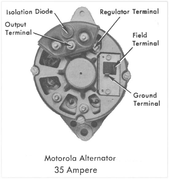 Note in this photo the bottom of the picture you can see the insulating washer between the longer 55 amp isolation diode and the negative diode stud, the upper part shows the keps nut directly on the stud and isolation diode. 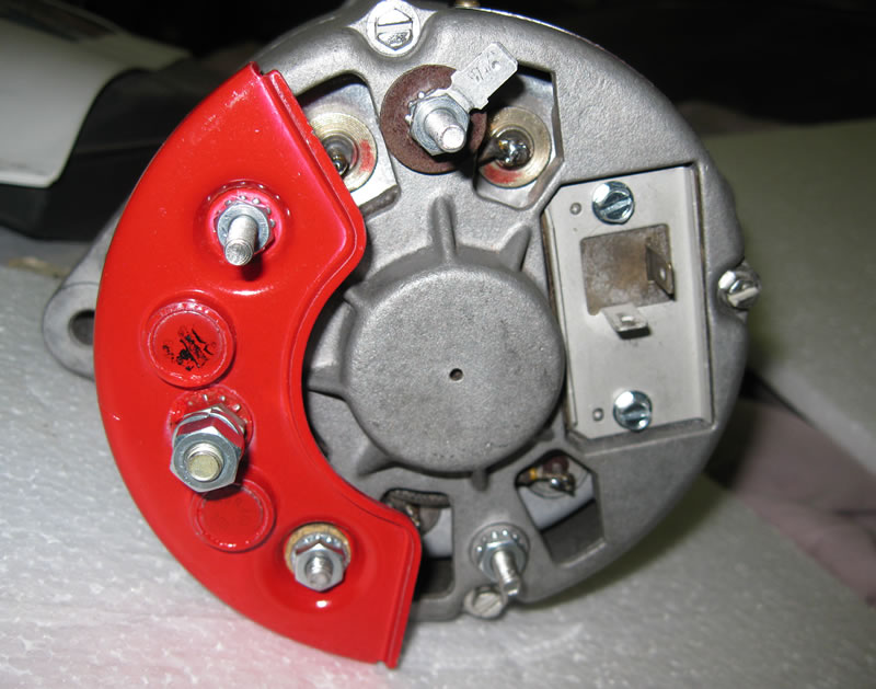 In this picture the two studs closest to you are - on the right the negative diode stud and on the left the positive diode stud. Note on the right stud a washer and a nylon sleeve - this is to insulate and isolate the longer 55 amp isolation diode from the negative stud. They want it anchored physically but NOT connected electrically, while the stud on the left is positive output so it does need to be physically and electrically connected to the isolation diode.  Again - note the insulator on the right, but on the left the nut cuts directly to the isolation diode.  OK, these are the two studs that come up from the positive diodes inside. They are identical, they are both pressed into the diode heat sink, both insulated from the case or frame (note the fiber washers) and the one on the left is what you normally connect to for the reg/aux orange wire - the one on the right is what you moved it to - ah, but they are the same. Those two studs form the legs of sort of a "U" so one leg is simply the left leg of the same U while the other is the right leg of that U. 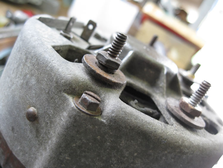 Here's another view - both of these studs put out exactly the same thing - except one has a connector for the orange wire while the other is connected to the 55 amp isolation diode.  On the 35 amp because the diode mounts over BOTH positive studs, they provide a place to connect the orange wire -  So the only difference really between the 35 and 55 is how they mount the larger isolation diode for the 55 - all other wiring would be the same electrically. The rear frame has two holes that are larger - at the top in this picture - for the nylon insulating sleeves, the lower holes in this photo are for the negative diode studs, they connect to the alternator frame so are not insulated.  And finally, I'm now confused because you basically moved the orange wire from the stud on the right to the stud on the left - both protrude from the frame or case through nylon insulating sleeves. Note the differences? Yeah, there aren't any.......  I am always nervous with remanufactured electric, carburetors and brake parts......... Unless the wiring harness is wrong for a 1970, I can't see how the regulator could be wrong unless they really messed up - wrong part in the box, etc. One would over-charge and the other would undercharge due to the 1 volt drop across the isolation diode. A 1971 regulator on a 1970 alternator would under-charge, a 1970 and earlier regulator on a later alternator with no isolation diode would over-charge. |
|
|
|
|
S Curry
AMC Addicted

Joined: Aug/16/2012 Location: Iowa Status: Offline Points: 598 |
Post Options
Thanks(0)
Quote Reply
Posted: Sep/28/2015 at 8:21am |
|
Just one question for billd. Is the red paint on the isolation diode holder anything special? Like Glyptal? Paint all flaked off of mine.
PS. great explanation and pictures! |
|
|
SC
|
|
|
|
|
71 Javelin AMX O.O.
AMC Addicted

Joined: Aug/29/2008 Location: Minnesota Status: Offline Points: 655 |
Post Options
Thanks(0)
Quote Reply
Posted: Sep/28/2015 at 8:48am |
|
How about something as simple as the body ground? I was getting no charging on my alt gage in my 1971 Javelin AMX when we started it up the first time. My buddy said to check the ground from the engine block to the engine crossmember. I had powder coated the front cross member so the eyelet was not grounding. We did the same with the starter, but that was obvious when the starter would not turn over.
Might be as simple as that?
Steve
|
|
|
|
|
billd
Moderator Group
Forum Administrator Joined: Jun/27/2007 Location: Iowa Status: Offline Points: 30894 |
Post Options
Thanks(0)
Quote Reply
Posted: Sep/28/2015 at 10:29am |
The red paint on originals is normally pretty tough, doesn't come off easily. On the other hand I wonder if now and then they painted some that weren't completely clean as the paint does seem to flake off. Most of the originals, including on alternators, new old stock in boxes or those on NOS alternators, almost appear "Dipped" as there is almost always a run or sort of a drip formed on one of the edges. Otherwise it appears as ordinary paint. They were colored according to voltage and polarity but since the after-market didn't follow the paint color codes, you may see colors Motorola never put out - or some of the manufacturers painted either the alternators or parts of them colors as they wanted/needed. Red is stock color for 12 volt negative ground. |
|
|
|
|
billd
Moderator Group
Forum Administrator Joined: Jun/27/2007 Location: Iowa Status: Offline Points: 30894 |
Post Options
Thanks(0)
Quote Reply
Posted: Sep/28/2015 at 10:41am |
That can definitely affect or impact accessories, etc. as they often ground through the body of the car in some way. As an isolated system in itself, if the battery - goes to the block and the regulator is properly grounded to the alternator through the black wire from regulator to alternator, it would still function, but the rest of the car wouldn't necessarily realize it! If battery neg goes to the block, the alternator is bolted to the block and is thus grounded to the block and through the block to the battery, and the regulator is properly connected to the alternator through the black ground lead, it would charge and should charge properly as far as keeping the battery up - but the accessories would struggle. The alternator and regulator connect directly to each other and to the battery so you could lift the engine out of the car, unscrew the regulator from the inner fender and hang it on the engine stand by string and as long as the battery was still cabled to the block and the alternator was still connected output to battery POS via the starter solenoid battery-side terminal, it would work fine. But a volt meter connected to ground through the chassis would read low voltage due to the voltage drop caused by the poor or lacking engine to chassis, and thus engine to meter, ground. The biggest problem is with accessories or items that draw appreciable current because smaller things can ground to the engine though throttle cable, drive shaft, etc. -poor but works for low draw items, while bigger things, such as the starter, etc. will typically fail. The volt mater may work but may read low because of the lack of meter ground to block. My own 73 Javelin has brighter headlights now since I put a cable between where the battery NEG bolts to the engine block and the chassis at the crossmember. The bolt was in the cross-member but there was nothing connected to it! I thought why the heck would anyone put a bolt, washer and nut in that hole - with it holding nothing, no cable, nuttin'. Silly, then why bother putting the crazy bolt back in? Due to the headers and extreme heat in that area I used a long heavy cable from the front end of the block where the battery negative bolted, up and then down to the chassis avoiding the headers. I still smelled hot wire insulation after a short drive with it. But it seems ok, and the headlights are brighter now, too. I think it was grounding via the throttle cable as when I put the NOS alternator and NOS regulator on the car I noted the throttle was far harder to push than it was before. The PO put the cable down too far so it's hard to push the throttle the first little bit then it get very easy and you take off like a shot, but after the new alternator and regulator I almost had to stand on the throttle to get it to respond. I suspect it was getting the throttle cable hot with the load and sort of messed it up. Man does that thing crank very nicely now and the beast starts like never before. Amazing what good a decent ground does for lighting, ignition systems/spark and so on! LOL |
|
|
|
|
iapexl8r
AMC Addicted
Joined: Apr/13/2008 Location: north idaho Status: Offline Points: 639 |
Post Options
Thanks(0)
Quote Reply
Posted: Sep/28/2015 at 11:02am |
|
Ok I understand but just had mental speed wobbles. they just rotated the isolation diode due to it being longer. So what is happening makes absolutely no sense. wonder if I have a connection issue of some sort. The BATT ground is ran directly to the engine and the factory engine ground to body is in place. I will perform a wiggle test next and meter the aux terminal on the ALT as well a a ohm check of engine to chassis. depending on results may remove ALT and shoot the aux terminal to the other isolation diode + terminal for resistance. Billd thank you very much for your technical expertise, with out you I would feel blindfolded for sure.
Chris P.S the alt currently on car has no tag, it must have been removed at some point I was mistaken. |
|
|
|
|
Post Reply
|
Page 12> |
 Tweet
Tweet
|
| Forum Jump | Forum Permissions You cannot post new topics in this forum You cannot reply to topics in this forum You cannot delete your posts in this forum You cannot edit your posts in this forum You cannot create polls in this forum You cannot vote in polls in this forum |


 Click for TheAMCForum Rules
 Topic Options
 S Curry wrote: