73 Javelin brake and suspension project
Printed From: TheAMCForum.com
Category: The Garage
Forum Name: Suspension, Steering, Brakes & Wheels
Forum Description: What makes it stop, turn, and smooths the ride
URL: https://theamcforum.com/forum/forum_posts.asp?TID=92968
Printed Date: Apr/19/2024 at 5:57pm
Software Version: Web Wiz Forums 12.03 - http://www.webwizforums.com
Topic: 73 Javelin brake and suspension project
Posted By: billd
Subject: 73 Javelin brake and suspension project
Date Posted: Mar/09/2018 at 6:55pm
|
This isn't going to be to the same level that I took my 70 to as this car is very modified and has had a rough prior life. I'm attempting to give it the TLC that it needs, priority making it safer but nicer as I can. The car came to me with power DRUM brakes. 73 Javelins had ten inch front drums. The brakes worked fine but I gave my front brakes, spindles and all, to my neighbor for his car as I figured I could use the disks of an 80 Concord wagon I'm parting out. Well, yeah - it was REALLY rusty so the shields were mostly gone, rotors very rusty (could be cleaned up I'm sure as they have not been turned before) but it was just a bit much by the time I spent money on all new bearings and seals, new calipers, new pads, having rotors turned, hoses and so on, It wasn't going to save me all that much in the end especially when I considered the time spent. So I bought the disk brake package amxess had for sale here in the forum and brackets from mrblatzman (both Steve and Bob great to deal with and good parts) There was no use doing all of that and not deal with the worn out bushings and other parts - the car has over 90,000 miles and again, had a rough prior life. So, similar to my 70 the entire front suspension is coming off,, all bushings being replaced, ball joints, tie rods, front springs (one was broken and they had twist-in spacers in the coils) But most parts will be painted and not powder coated like I did with my 70. With that car I powder coated almost everything including the coil springs! This will be a sort of show car, but mostly a fun car. the process started a full year ago when i told my neighbor that if he'd come over and pull the front brakes and spindles he could have them. It's been up on stands all this time. Time to get it finished up and back on the road. As you can see here - the strut rod bushings are TOAST. One was literally mushy and falling apart. (and started to wear the bracket hole) The lowers are from my 70 - I put NOS lower control arms on it and saved those because at that time they had only about 25,000 miles on them. So I cleaned and painted them and put in new bushings. The uppers are CRUSTY, greasy, nasty and will take a couple of hours just for basic cleaning. Spring supports are rebuilt and nice with new bushings and fresh paint. Most parts are here except upper ball joints and those are coming from Amazon the first of next week.  Maybe you can see the PO patched the battery area, not really well but better than a hole I guess.  Left side - haven't gotten the control arms off yet - do have one of the bolts out of the upper. Have to scrape tons of grease and gunk before I can get the lower off this side......  Parts, some ready to go...  More parts and the springs from another 73 I'll be using...  Spring supports all rebuilt and ready, most of the new suspension parts......   -------------  http://theamcpages.com" rel="nofollow - http://theamcpages.com http://antique-engines.com" rel="nofollow - http://antique-engines.com |
Replies:
Posted By: 304-dude
Date Posted: Mar/09/2018 at 7:40pm
|
Billd, i dont think anyone here will make a comment on what works best, or how they would substitute for a diff part. Most of us will just sit and watch with a beer in hand to see how you go about a complete front end rebuild, it a rarity on the forum, as most threads are varied in depth. I did not notice if you plan on tie rod ends and steering as you are deep in the parts replacement area. We pretty much know you will pay good money for parts that are proper or in this particular case, are worth buying. IMO NOS is best and can be more economical in the long run. As NOS parts can be 2x or even 3x the money for your average part. I think you have been very vocal on keeping up on clarifying other people's threads, expecting the new or less experienced to know reasons why one did or chose something, when not pointed out or overlooked in discussion. Not sure, but i do believe you chose old stock Moog over new? Not that we are to have a long drawn discussion on pros and cons, just it may help to have some help on parts selecting if, you had to obtain bushings, brake components and ball joints from a fresh at home rebuild. Just thinking out loud, as it is early and enough time to put some input in on your thoughts before things may jumble around. ------------- 71 Javelin SST body 390 69 crank, 70 block & heads NASCAR SB2 rods & pistons 78 Jeep TH400 w/ 2.76 Low 50/50 Ford-AMC Suspension 79 F150 rear & 8.8 axles Ford Racing 3.25 gears & 9" /w Detroit locker |
Posted By: Lyle
Date Posted: Mar/09/2018 at 8:35pm
|
Bill, You probably know you are missing the top polymer on the torsion bar in your picture. If you haven't already ordered the parts, Mustang torsion bar connecting bolts are the same and cheaper to buy the bolts and bushings set then just the AMC bushings. Have you taken the fenders off and looked at the troughs? They are structural and can be repaired. The gas line going through the frame - have a good look, mine was half eaten/worn away. Dust shields I made myself, 18 gauge and a bead roller. Template was the old rust shield - all it was good for. A little tighter to the disk but no issues. If yours had the same tough life as mine check the frame for square and bend. Mine was out of square 3/8" and 1/2" twist. Braces and Enerpack got it back, alignment 0.01° thrust line and 0.002° front to back frame. Mine came with sub frame connectors so I cut them off and replaced with same (new fabrication) after straightening. Mine was never registered for the street so I believe it was race or other special order, just guessing by the twisting, sub frame connectors, rear end yanked out more then once and transmission casing pieces ripped into the rockers. Have fun:) |
Posted By: billd
Date Posted: Mar/09/2018 at 9:56pm
|
Lyle I wish you could have seen the link on that bar on the right side...... the bolt had broken and hammered on the lower part so much it had worn it smooth and the upper part still in the bar was now bent and worn smooth. Obviously it had been broken for a lot of miles. I knew it was broken but was waiting until it was all apart. I thought I had a link kit (the long bolts, spacers, washers and rubber bushings) from another project I didn't need..... if I don't. For one of my other cars I bought a kit at NAPA - it was less than twenty bucks and since they are pretty universal, I just told them what I wanted, no need to specify the car. On the dust shields - I have none. The ones from the Concord I was GOING to use the brakes from were so rotted there wasn't anything to get a pattern from. Fourth photo down shows remains of the better one in the far left part of the picture. And those were Bendix brakes. I bought the heavy-duty KH brakes from amxess here on the forum - the setup he had for sale for 300. He had everything except the shields - so I'll be looking for a pair. I have NO shields at all - nothing, zip - I really would want shields because they also help with road splash,, etc. and it rains a lot and our old roads hold water and the roads are dirty after winter's sand trucks keep laying down a beach worth of sand each winter. So if I can find the proper shields for THESE brakes, I'd be happier. I don't have to pull the fenders to know about the gussets - the front ends are rotted about an inch or two back from the front. They appear solid otherwise but the left one is also needing attention where it joins the car at the back - I can stick a finger between the back end of the gusset and the firewall area up in the wheel well. And I know the right front has been welded back of the headlight and where the upper rad support connects. I will be pulling fenders in the future, but I know I need to work on the gussets at the front and on the left side, MAYBE at the rear. (I REALLY wish I was a much better welder!) The car seems straight - things line up really nice, no odd gaps, no broken glass - all original glass, tires didn't wear weird (odd for the shot bushings I'm finding) Anyway, I DO need to replace or rather REPAIR the gussets - I suspect only the front couple of inches. I have a NOS left fender, would LOVE to find a new right fender as well. My take on the car after owing it for 2.5 years is that it sat for several years,, the prior owner did some patching, replaced carpet, replaced the floor sills (and left out the seat belt anchor points but that's another topic!) Basically the car is an unfinished project - and the PO said as much. He was a paint guy, not a mechanic and was really bad with electric and interior work. All I'm missing are the upper ball joints - and I think I have the "sway bar" links in a tub of parts. It needs shocked (one was broken and the other was bent and had zero resistance up or down) 304 - I know it was impossible to tell from the photo because it was all boxes and such - but there are two inner and two outer tie rods in there, new sleeves and clamps and bolts and nuts. I did forget to order an idler arm but I haven't checked this one yet - it will likely get replaced either now or soon ,but the tie rods - all four ends are already bought and in those boxes. I had NOS lower control arm bushings but it's not wear or use - it's AGE that also kills rubber parts, so I opted to not use the NOS bushings when I saw one of them already had a crack starting. I had two sets of upper control arms on the shelf and the arms still in the Concord besides those in this car - will pull them all and lay them out and choose the best of the four sets/pairs to use. Calipers brand new, rotors brand new, bearings and seals brand new, pads brand new, caliper brackets new, hoses brand new (and bought the rear brake hose too while I was at it) so all brake hoses will be new. I plan on new brake lines, especially after seeing the brown/gray mud that was in the old master cylinder. Can't flush that out well enough. I laid the Concord rotors on my bench next to the NEW rotors and it appears like I may have to space my spindles out about two washer thicknesses - that's a GUESS only, based on how the surfaces of the rotor sit compared to the bearing areas. I'll know that later when I dry fit everything. I plan on doing a dry fit, mocking things up, not tightening anything until I see how things fit and where I may need spacers. Again, it won't be the perfect pain-staking restoration of my 70 front end, I spent a ton of time, efforts cleaning and totally de-rusting, powder coating, NOS control arms and more, on that. I left no stone unturned. It was also a 25,000 car when I did that so there wasn't wear, it was just time and bushing rot that needed fixing there. Even the cross member got blasted, treated and powder coated on that car. I cleaned every part one at a time in my electrolysis bucket, phosphate treated, powder coated, etc. This will be good, it will be safe, it will be better than it ever was before (the HD disk brakes will see to that) but it won't be an AMO show car. On the other hand I am already struggling with "where do I stop" and having to really try very very hard to resist the urge to make it perfect. My Eagle was supposed to be a "get it on the road and paint it" daily driver car and ended up with a car good enough to get a high score at AMO (and a trophy) I just MUST resist the urge to do this one to such standards......... I may need someone to come by and hold me back on it now and then. I cant afford the time and money to do another car like I did that one. (and it's STILL not done - I have another tub of NOS parts to put into it) ------------- http://theamcpages.com" rel="nofollow - http://theamcpages.com http://antique-engines.com" rel="nofollow - http://antique-engines.com |
Posted By: 304-dude
Date Posted: Mar/10/2018 at 5:13am
|
About holding back... one thing that may help. Always keep function a priority, limiting on how much does perfect look effect costs. But it seems your wife knows you best, so have her manage your car. Tell her what's most important... safety, and proper fit with a limit on costs, having comparisons of what is available. Then she either OKs or disproves. I know you cannot help your self with being use to doing things your way on your car's and others. Spend time with my cousin, and eventually seeing how he can do things on bare minimum, can break your locked in thoughts of what is proper. Not saying an old rusty item will do the job just as well... Seems you broke me from commenting on ideas on not using NOS, because your locked in on it. I don't see the parts you got as an issue, but in some ways, they be over kill, only by that they are NOS. Considering you may have saved some coin in hunting at the next swap meet, your standards my have made 3 events unfruitful. So taking the plugs to get such parts is a bit of a god send. The best example I could think of is my parts I sold from my car. I could not replace them to the same or better without some extra costs, if i were to return it back to stock. Not that I sold low, just by overall condition. Even back then in 2005 not every thing being offered was of 80s and 90s condition. An easter egg hunt for most, and especially now. I am lucky with being able to keep things frugal while still opting for the better made products available over the counter. Time to be so was and still is not part of the equation. Knowing you want to get it done, makes time part of your equation. Ah, about NOS bushings... i understand about that, and has been part of your posts here and there... you just cant trust old rubber to stay perfect over time, no matter NOS or od stock OEM replacements. Just assumed you got a good OEM replacement set from NAPA or whoever. ------------- 71 Javelin SST body 390 69 crank, 70 block & heads NASCAR SB2 rods & pistons 78 Jeep TH400 w/ 2.76 Low 50/50 Ford-AMC Suspension 79 F150 rear & 8.8 axles Ford Racing 3.25 gears & 9" /w Detroit locker |
Posted By: Lyle
Date Posted: Mar/10/2018 at 6:36am
|
NAPA - arggg! - new engine seals installed and leaked after 2 months of service. Still had the boxes, 18 year old seals by the date code on the box, looked after the fact - dumb I know. In the Nuclear industry they didn't last two years on the shelf and were changed every 10 to 12. Yes, old elastomers are just that, expect reduced service life. |
Posted By: billd
Date Posted: Mar/10/2018 at 7:52am
|
Lyle - The sway bar links I bought were basically exactly the same as the originals I took out of my 70 and they are still i the car and still look like new.. There's little that could go wrong there unless it was a cheap grade 2 bolt or something. However, that was years ago so........ and yes things like seals and rubber parts - beware and check dates, dust on the box, etc. I hear ya. Dude I have no clue what you are really trying to say - as they used to say on Laugh-In "you lost me at the bakery". Totally. As far as doing something right - that's the only way I know. Part is my education and history - been at it since age 14 and worked for two "old timers" who were the very best in the game. You never wanted any come-backs. Besides - no, I can't do any other way and no, crusty/rusty parts won't do. You have no clue as you have not dealt with ADHD nor are you OCD. When someone sends something my way they know when they get it back it will work, it will be right. Now some things I understand about not being able to use the very best first time - sometimes something can't be had or there's no money - but suspension, steering and brakes are one thing I will never do a second time. If I can't do it right once - I wait. I don't mind swapping out marker lights, tail lights, trim, a clock, seat trim, a door handle, but other things it's DUMB to do it two times. Why spend hours on something and then later do it all over again. Do you enjoy taking out springs so you can swap parts and spending half a day doing it again? Not sure where the constant talk of NOS keeps coming in - nothing in the pictures was NOS except perhaps the tie rod sleeves (and I wasn't trying, there) or perhaps the rear brake hose brass block (again, not trying, it was the first thing I found) Otherwise NONE of the brake parts - NONE - are NOS. They are NORS. Not one of those parts came from an AMC dealership in AMC boxes. The only NOS brake parts are what I got from Bob - and again, I'd have taken used ones but good luck - all I could find at the time were what Bob had and his price matched what used ones would have likely sold for on eBay. Can't beat a brand new bracket for twenty bucks - did you have a set you'd have sold me for that? Did you LOOK at the pictures? Do you know what those yellow boxes are? Not NOS. The calipers and their brackets were painted silver - hardly NOS. New parts, yes - but not directly from the AMC factory. They are nice, EXCELLENT parts and a great deal. I knew what I was getting and am 110% happy with them and would do it again. But new, not NOS. I don't want amxess/Steve to get the wrong idea - I KNEW what the parts were and that is why I bought them. The deal was good, the parts were very very good and I'd do it all over again. These will make GREAT brakes and I'm TOTALLY happy with the deal AND the parts - ZERO negatives there. (Of course we know AMC didn't make their own brakes so you could hardly truly buy NOS brake parts.) I'm simply trying to explain to someone who apparently doesn't get it that I wasn't holding out for NOS parts and geesh, I shouldn't have to justify what I'm doing to a certain person on every single project.
Why do you keep trying to tell me how to run things? Really, I get a lot of lectures but you don't know me or my work. I've done this probably longer than you've even been driving. My wife always says "do it right or don't do it at all" and "don't cheap out, you know you'll just end up buying it again later". She's a perfectionist. (you'd know that by now if you paid attention and stopped trying to train me) I was half-joking, a point those who know me or try to would have gotten and understood. But again, I know one way of doing something, and that's safe and right. The finish or removal of rust, etc. is a matter of my "medical situation" and cannot be changed, at least not easily. (too bad more people don't strive for perfection or totally enjoy a job well done to the best of their ability) Anyway, PLEASE REFRAIN - this is about my car and how I am doing it - not your attempts at psycho-analyzing things. I am truly absolutely afraid to post a thing about my projects for fear you will pop in with a rant about me, my personality and how I do things. My fears were not unfounded.
Wow, I was right - you are clueless and TOTALLY wrong. Why do you keep trying to TEACH ME when I have taught this stuff to others over the years? I'll put my knowledge of cars up against you any day of the week. First, those are NEW parts, not "old stock Moog". good grief - you really don't have a clue. The last thing I need is you telling me how to select parts. How the heck long have you been doing this? Me since the early 1970s - and I have the trophies to prove it and the certificates and the degree and the letters of recommendation. Did your state's biggest AMC/Jeep dealership call you out of the blue and offer you the service manager position - based only on reputation? Did you ace the Plymouth Troubleshooting written test- a record never broken, and set record time to judging with only one point lost (a hose was above another in a clip and they should have been reversed in the clip but the connections were correct) I've done more suspension and brake work than you'll ever do in your life - I used to make my living at it. Why is it that you keep trying to fix me when others, like Lyle, Red Devil and others are very helpful with solid information? Sorry, folks, but I'm at wit's end with that BS. I may or may not post again in this thread. ------------- http://theamcpages.com" rel="nofollow - http://theamcpages.com http://antique-engines.com" rel="nofollow - http://antique-engines.com |
 About holding back... one thing that may help. Always keep function a priority, limiting on how much does perfect look effect costs. But it seems your wife knows you best, so have her manage your car. Tell her what's most important... safety, and proper fit with a limit on costs, having comparisons of what is available. Then she either OKs or disproves.
Posted By: billd
Date Posted: Mar/11/2018 at 4:11pm
|
Just couldn't help myself - was doing some other parts for other projects and decided, what the heck, can't stand rust on tie rod sleeves. I've done too many dozens and dozens of alignments where the sleeves were rusted to the tie rod ends and have to heat or beat or whatever. Not these - and they sure do look pretty. Also plated the threaded end of the right strut rod to help slow any rust........ will do left after I get it removed and cleaned up. Yellow bright zinc on the sleeves and black zinc on the clamps and yellow zinc grade 8 bolts and lock nuts.   ------------- http://theamcpages.com" rel="nofollow - http://theamcpages.com http://antique-engines.com" rel="nofollow - http://antique-engines.com |
Posted By: pit crew
Date Posted: Mar/11/2018 at 5:15pm
Over the top Bill. 
-------------  73 Hornet - 401EFI - THM400 - Twin Grip 20 |
Posted By: billd
Date Posted: Mar/11/2018 at 8:53pm
Ya really think so? Man, they sure are pretty in person. Hey, if the interior can be Pierre Cardin, the underside can have some art, too. If I had time I had actually thought about bright zinc plating some of the suspension parts - naw, would take forever. The rest will get painted. ------------- http://theamcpages.com" rel="nofollow - http://theamcpages.com http://antique-engines.com" rel="nofollow - http://antique-engines.com |
Posted By: LakesideRamblin
Date Posted: Mar/11/2018 at 11:16pm
|
Those sleeves are perty! Never have seen how you or anyone else zinc coat parts. Would you mind showing a picture of that process. Very curious. Thanks. ------------- LakesideRamblin 69 Rambler 360 73 Javelin 360 "If you could kick the person in the pants responsible for most of your trouble, you wouldn't sit for a month." T. Roosevelt |
Posted By: pit crew
Date Posted: Mar/12/2018 at 7:21am
 ------------- 73 Hornet - 401EFI - THM400 - Twin Grip 20 |
Posted By: billd
Date Posted: Mar/12/2018 at 9:21am
|
Well honestly I have come to EXPECT that sort of attention to detail and those fun little things in the stuff you do. For the plating, you start with lots of cash - Nearly $700 for the plating rectifier or power supply (in my case, a programmable digital power supply) About $1300 for certified 99.99% pure zinc bars which I cut into slabs to fit my anode hangers and will fit into the anode bags. About $25 for anode bags - special filter bags the anodes are placed in before hanging them in the solution - it prevents zinc sludge and crap from getting suspended in the solution and making the plated surfaces rough. Hangers and stands to suspend the parts to be plated from - in the solution. I made my hanger stands and made the hooks and racks using brass and copper which you MUST nickel plate to prevent copper contamination of the plating solution. Some have their racks coated with a special plastic but I did the nickel and then powder coated them to seal the copper and brass away from the plating solution. About $800 worth of chemicals - 200 of that is common ammonium chloride, zinc chloride and potassium chloride I order from various sources and the other is the proprietary chemicals I buy from an international plating chemical supplier. I work with their chemists, etc. when I run into any issues. These can only be shipped via freight and to a business address due to their nature. Then there's a supply of ammonia and HCL to keep the pH of the bath at about 5.3 - add acid if it gets too high, ammonia if it gets too low - doesn't happen often but there's "drag-in" from the pickle bath or metallic and other contamination that can happen. I've had to balance the pH a couple of times in the last two months or so. A supply of disposable rubber gloves, plastic aprons (remember, it's ACID), goggles and such. Tons of water for rinsing between every step - DISTILLED water for many steps. An acid bath for stripping zinc, etc. A special caustic cleaning solution run at about 180 degrees to clean the parts of any grease, oil or other similar substances. A few hundred bucks worth of the various chromate or passivate solutions - yellow passivate, clear/blue, and black are mostly what I use. Each has to have it's own "tub" or container and the yellow I run at about 100 to 120 degrees. Parts must be beyond perfectly clean and pass a water-break test - water must NOT bead up on the cleaned metal surface. It must evenly wet the surface and not bead. So you strip all rust, dirt, whatever and get it so clean you can't see a speck of rust anywhere. You soak it in the cleaning solution, then rinse it, then remove any prior plating using acid, rinse the heck out of it (and I double-check after this, often going back to the caustic hot solution) then sort of depending - a judgement call IMO, a pickle solution consisting of a special mild acid that activates the steel or iron or cast zinc item to accept plating more readily. Then the part gets hung from my hanger on those special hangers and rods and hooks I've made and put into the plating solution/bath. I apply the power to the zinc anode racks and to the part/parts to be plated via their hanger/rack - I have to know the surface area of the part so I calculate that and apply a formula so that I apply roughly 15 to 18 amps per square foot. Now on smaller parts - I do end up using a calculator and often work with power in the tenths of an amp. The two sleeves I ran at 3 amps for 40 minutes (programmed my plating rectifier for that) and the clamps I ran at just a bit under that, but close to 3 amps. I've done small parts at .25 amps and as much as 14 amps. I can go as high as 25 (I think it's 25) with my plater. Once plated, I rinse the part, NEVER TOUCHING IT, run it in the passivate - the sleeves in yellow, the clamps in black - and do a very light rinse then hang them for 24 hours to dry and set. The passivate is very fragile at first and if you touch it or mess with it at all you start over. I haven't calculated my total costs but it's in the thousands. Oh, I nearly forgot - you have to circulate the plating bath and filter it constantly. ANY fine material in the solution can cause roughness. So I have two small filters and three pumps circulating the solutions. Luckily I can use CHEAP stuff there - aquarium pumps work fine if you get enough GPM out of them. I have to keep the plating tank at 80 degrees and aquarium heaters for for that as long as they are glass or some other very neutral material, and I use aquarium heaters. I have to use stainless steel tank heaters for the passivate as it's harder on stuff. ------------- http://theamcpages.com" rel="nofollow - http://theamcpages.com http://antique-engines.com" rel="nofollow - http://antique-engines.com |
Posted By: billd
Date Posted: Mar/12/2018 at 9:23am
|
Heading back out to the shop soon - got the right lower arm mounted and some of the right side parts cleaned and painted yesterday. The upper ball joints should arrive today. The upper arms are a mess - so we'll see............. even my best pair have rust and a few imperfections and have years of dirt, grease, paint - some multiple layers applied by others, and other crud Can't wait to get even just one side back together! ------------- http://theamcpages.com" rel="nofollow - http://theamcpages.com http://antique-engines.com" rel="nofollow - http://antique-engines.com |
Posted By: pit crew
Date Posted: Mar/12/2018 at 10:47am
------------- 73 Hornet - 401EFI - THM400 - Twin Grip 20 |
Posted By: billd
Date Posted: Mar/12/2018 at 5:22pm
Amen - ain't it the truth. I got the strut nuts cleaned up and plated looking not quite like new because of some minor pitting but still really nice. A few more parts cleaned up painted, etc. Here's the control arms from the right side- I had mentioned earlier that the right sway bar link had broken and was hammering on the ends etc. - you can see where it not only broke but the top part constantly hitting on the lower part and the arm wore it in an interesting way. Also a photo of the Kent Moore tool used to remove and replace upper control arm bushings. A press can be used but is rather inconvenient. I used my press on the lower arm bushings and I use this tool for the upper arm bushings........   pit crew this pic is for you  ------------- http://theamcpages.com" rel="nofollow - http://theamcpages.com http://antique-engines.com" rel="nofollow - http://antique-engines.com |
Posted By: pit crew
Date Posted: Mar/12/2018 at 9:08pm
Pretty. Not a show car huh?  By the way. If the lower control arm is too beat up check part number  ------------- 73 Hornet - 401EFI - THM400 - Twin Grip 20 |
Posted By: billd
Date Posted: Mar/12/2018 at 10:03pm
|
I think the lowers are ok, but I had saved the original lower arms from my 70 when I rebuilt the suspension on it and put in a pair of NOS arms I got (with riveted in ball joints, etc.) The car had only 25,000 miles on it when I pulled the arms - they were dirty and needed a lot of cleaning and so on and wouldn't have powder coated as nicely as NOS but I wrapped and saved them. I cleaned them up pretty good (actually most folks will never see the rough spots) and have used those arms for the lowers on this car. Now to worry about the uppers - which are a mess - rusty and dirty. Ha - with those struts you'll not need to worry about bushings ever again. talk about heavy-duty. ------------- http://theamcpages.com" rel="nofollow - http://theamcpages.com http://antique-engines.com" rel="nofollow - http://antique-engines.com |
Posted By: CamJam
Date Posted: Mar/12/2018 at 11:01pm
|
Just did this on my '72 Javelin... new coil springs and all. What a difference! The car was scary over 50 mph before... drives like new now. Everything on my front end is new now except the inner tie rods (they seemed ok). The mid-90s Grand Cherokee steering box is something I highly recommend too. And yes, your earlier front-end rebuild thread was a big help to me. ------------- '73 Javelin 360 (current project) '72 Baja Bronze Javelin SST '69 Big Bad Orange AMX (2018 Teague Heritage Award) SOLD  |
Posted By: billd
Date Posted: Mar/13/2018 at 5:25pm
|
Here are pics of the strut hardware I refinished. The strut bushings I have didn't come with the concave washers so I had to spend a hour cleaning these up well enough to plate them. Can't even remember where I got these bushings but they are new, not in any boxes, but without the large concave washers so had to reuse my rusty, greasy, thick with flaky rust parts. I mean thee rust was so bad I had to dig out big flakes and scrape and blast and finally use a Dremel with grinder tool to clean them up. Also pics of the right side partially together - but I have a question - I did not take this apart, my neighbor did when I gave him the drum brakes. I did take apart the Concord I was going to use parts from but it was snowy, windy, wet and COLD when I did that OUTSIDE. I'm wondering about the thick flat washers and the split lock washers. There's only 8 of the thick flat washers and maybe that many of the old lock washers. My guess is that the LOCK washers were used with the drum brakes and the FLAT washers used with the disk brakes due to the thin splash shield. The locks make more sense with the drum brake thick backing plate. The thick flat washers make sense with the thin disk brake splash shields. I have the bolts, nuts and washers from two cars but there's not enough lock washers for two cars and not enough flat washers for two cars. So did these with DISK brakes use only the flat washers - and DRUM brake cars use only the LOCK washers under the nuts? And pics of an original DISK brake car to show which was used?? I stuck both on a couple just to keep things in place but I know that it was EITHER/OR and not both lock and flat on all four bolts - for one thing there aren't enough - but the flat washers show ZERO sign of a lock washer ever having been against it - they are too perfect. So I will guess - lock washers used on drum brakes, flat washers used on disk brakes due to the splash shield vs backing plate material and thickness.      ------------- http://theamcpages.com" rel="nofollow - http://theamcpages.com http://antique-engines.com" rel="nofollow - http://antique-engines.com |
Posted By: billd
Date Posted: Mar/14/2018 at 11:37am
|
No one has the correct information on which washers were used with DISK brakes in 73? Did they use the thick flat washers behind the nuts for the spindle, or lock washers? I'm pretty sure it wasn't both - I am guessing they used lock washers for the nuts for drum brakes and thick flat washers for disk brakes due to the thin splash shield vs. the thick backing plate for drums. Looking to find out which washers were used where - what was CORRECT for DISK brakes on a 73 - the bolts, washers and nuts used for the spindle to steering knuckle......... And pictures or description of what was used where? ------------- http://theamcpages.com" rel="nofollow - http://theamcpages.com http://antique-engines.com" rel="nofollow - http://antique-engines.com |
Posted By: Red Devil
Date Posted: Mar/14/2018 at 11:57am
|
Hi Bill, From Amxess post:
Can confirm the nuts and lockwashers on mine are all on the inboard side ... but honestly don't know if they have ever been removed. Don't know if there's room for washers under the bolt heads and clear the hub? Hope this helps,RD |


Posted By: billd
Date Posted: Mar/14/2018 at 12:06pm
|
Does your car have original disk brakes? Does it use lock washers or flat washers? I have two sets of the four bolts - four of them have lock washers and four of them have thick flat washers. This tells me that AMC used EITHER but not both on the same bolts - What I'm trying to find out if the conversion i'm doing I should use the flat OR the lock washers. The problem with the parts book is that it doesn't really say anything - and it shows two different directions which I've never actually seen. The same reference number shows EITHER lock or flat - so it doesn't say "lock washers with drum and flat washers with disk". The half inch bolts, the larger ones that hold the caliper brackets on use lock washers - that's a given since they don't use nuts but screw directly to the other brackets. So I know about those - bolts and lock washers But the four that hold the spindle on - flat OR lock washers - for disk? ------------- http://theamcpages.com" rel="nofollow - http://theamcpages.com http://antique-engines.com" rel="nofollow - http://antique-engines.com |
Posted By: Red Devil
Date Posted: Mar/14/2018 at 12:17pm
| Mine has the factory original KH brakes ... but don't know if they've ever been fully disassembled? In the 28 years or so I've owned it, I've only changed rotors, bearings, calipers, pads, hose and hard lines. Will have to pull a rotor to check as I forget if it had washers under the bolt heads? Definitely nuts on the inboard side, and pretty sure with lockwashers ... but need to double-check. |
Posted By: billd
Date Posted: Mar/14/2018 at 1:29pm
|
Looking at the steering arms and the knuckle it appears only cap screws (bolts) and not flat washers because there's a pattern that fits the tiny shoulder or ledge under the head of the bolt (making it a cap screw, technically speaking) If there was a washer under the bolt head I'd not expect that pattern in the cast parts. COULD BE WRONG of course! ------------- http://theamcpages.com" rel="nofollow - http://theamcpages.com http://antique-engines.com" rel="nofollow - http://antique-engines.com |
Posted By: billd
Date Posted: Mar/14/2018 at 1:35pm
|
OK, it's warm and dry enough I went out to look at the concord. Those parts are still sitting and laying there under the car, uncleaned. I appear to be very wrong - The pattern in the RUST and dirt would indicate fat flat washers on the bolts first, then the bolts were slipped in, then lock washers at the spindle. So if the CONCORD was correct, it was bolt head, flat washers, steering arm and knuckle, spindle, then lock washers and nuts. (I left out the disk shields because I don't have any!!) Good thing I bought new grade 8 lock washers. So they did use both. Interesting. Flat under the bolt head, lock under the nuts. There's PLENTY of bolt length and in fact it would be better with both because the bolts would protrude more without them. ------------- http://theamcpages.com" rel="nofollow - http://theamcpages.com http://antique-engines.com" rel="nofollow - http://antique-engines.com |
Posted By: billd
Date Posted: Mar/14/2018 at 4:56pm
|
I had to have the nuts totally snugged up to clear the rotor - if they were loose at all they rubbed - the lock washers of course pushed them out. I pulled the rotor off and tightened the four bolts for the spindle and put the rotor back. I then tried to mount the caliper to see how things would fit and - wasn't able to get the caliper on. The outboard pad was too tight against the rotor meaning that the rotor was out too far. When I did get it sort of mounted and snugged things up it was almost impossible to turn the rotor because the outboard pad was against it. There was plenty of space on the inboard side of things. The verdict - I have to machine the mounting area of the spindles to move them back inward so the rotor would move inward and give clearance. I have the right spindle almost done but stopped for the day. I've taken off about 1/8" so far and will take off a bit more and try it. I'll keep track of the dimensions - how much I had to remove compared to the original thickness of the spindle mounting pads and document that. Otherwise things appear ok so far. Sure glad I can machine those myself!! That way I can take some off and try it etc. The good news is - NO WASHERS - of course unless I screw up! The worst part is cleaning and prepping and painting parts - blasting, solvent tank, wire brush, ugh. I used my press to install the bushings but it was easier to install the sleeve with an original tool....     ------------- http://theamcpages.com" rel="nofollow - http://theamcpages.com http://antique-engines.com" rel="nofollow - http://antique-engines.com |
Posted By: MD Racer
Date Posted: Mar/15/2018 at 3:15pm
|
You have the bolts on the wrong way. The bolt heads should be to the disc rotor side and the nuts with lock washers on the back side toward the engine bay. ------------- 1971 Javelin 1971 Javelin SST 1971 Javelin AMX |
Posted By: farna
Date Posted: Mar/15/2018 at 4:57pm
|
I was about to say the same thing! Disc brake cars usually have the bolt heads on the spindle side, drum brakes have nuts on spindle side. ------------- Frank Swygert |
Posted By: billd
Date Posted: Mar/15/2018 at 6:59pm
|
Farna is exactly correct......... the Concord had the bolt heads toward the rotor - the 73 Javelin which is what I'm putting disks on had the NUTS to the spindle and the bolts came in from the back. Farna nailed it. That is because the large nuts didn't clear the rotor back side. MD Racer is seeing my MOCK-UP phase - you don't put the bolts in through the spindle side when you are going on and off, on and off, fitting parts and machining the spindle, etc. Otherwise you have to pull the whole thing apart instead of simply pulling the spindle back off and leaving the bolts in place. And that brings me to my next "progress post". I machined the spindle mounting pads and got the rotor sitting right under the caliper. The rotor sat too far out as it was - put pressure against the outboard pad. So I machined until I got equal clearance pad-to-rotor on both pads when the caliper piston was fully retracted. In other words, piston clear in, pads in place, there is now the same amount of clearance between pad and rotor, inner and outer. To accomplish this I machined 0.100" off the back side of the spindles. It's taking forever - have to clean and derust parts, and some of the parts are really badly pitted and rough, and fitting things just right took a while. The right side is mostly together, the left is next....    ------------- http://theamcpages.com" rel="nofollow - http://theamcpages.com http://antique-engines.com" rel="nofollow - http://antique-engines.com |
Posted By: pit crew
Date Posted: Mar/15/2018 at 8:13pm
|
That all looks so clean and pretty Bill. Now you just have to clean and paint the springs to match.
------------- 73 Hornet - 401EFI - THM400 - Twin Grip 20 |
Posted By: billd
Date Posted: Mar/15/2018 at 8:20pm
|
I almost had to close my eyes when putting that spring in.......... but didn't want to take the time right now. Maybe in the future....... Yeah, I hated putting that thing in there like that. ------------- http://theamcpages.com" rel="nofollow - http://theamcpages.com http://antique-engines.com" rel="nofollow - http://antique-engines.com |
Posted By: Lyle
Date Posted: Mar/15/2018 at 8:45pm
|
Bill, Your post 5:56PM, picture #3, part #8.835-1 from Red Devil's image. The boss on the bracket that holds the caliper is thicker on one side then the other. Are these parts interchangeable left and right side? If that part was on the other side the caliper would be placed inboard more, away from the rotor. Not saying what your doing is not going to work but looking at the pictures, have to ask so others may not have to go through the frustrations your having. I used an 81 Concord setup on my 69 Javelin and didn't go through what your enduring. |
Posted By: billd
Date Posted: Mar/15/2018 at 9:35pm
|
Nope - the brackets behind the spindle that hold the caliper bracket are two different part numbers and have a machined surface that the caliper bracket itself bolts to. The caliper bracket has a recess the bolts fit into and a flat side machined on the other side that mates to the bracket behind the spindle. In short, the bracket behind the spindle that holds the caliper bracket and the caliper brackets themselves have a left and a right - and have different part numbers cast into them. 8.835-1 is what I bought from mrblatzman (Bob) and there are a left and right. Remember he posted one for sale and we determined the part number he posted I believe was the right - he also had a left he sold me. They'll only fit one way, one side. Besides, the caliper would have had to move OUT away from the engine bay to work - the outboard pad, the one closest to the wheel, was what was hitting the rotor hard. So either move the caliper out or the rotor in. Since the brackets could not be changed and only fit one side, the obvious choice was to machine the spindles. Were the calipers and brackets you used the same as these? Remember, I'm using spindles from an 80 Concord with Bendix brakes on a 73 car that had drum and am mounting heavy duty Kelsey Hayes brakes. AMC also changed brakes somewhere in 81 - and even 82. I found three different disk brake setups - the brakes from an 81 I parted wouldn't work on an 82 and both were different than the 80 Concord! I'm not really "going through" that much - I could have waited and looked for the correct spindles for the HD K-H brakes for a 73 but opted to spend ten to fifteen minutes each machining spindles. ;-) I did them myself - so there was no cost or travel time. ------------- http://theamcpages.com" rel="nofollow - http://theamcpages.com http://antique-engines.com" rel="nofollow - http://antique-engines.com |
Posted By: billd
Date Posted: Mar/15/2018 at 9:56pm
|
What's causing the most pain and taking so bloody long is the amount of RUST and CRUD under the car. Yeah, it looks slick, runs great, etc. but the PO did ZERO for the suspension, steering and brakes. In fact he totally ignored the mechanical and suspension aspect of the car - to the point some parts crumble as I remove them such as the clips that hold brake hoses to the frame bracket, and the small snubber mount bracket that bolts to the frame with three bolts - totally rusted and pitted and the rubber "snubbers" were GONE GONE GONE. Inside was a quarter inch of rust and crud. It takes a lot to get that out - with chisels and so on. Can't blast it as it's too hard. Even electrolysis takes a lot to get that stuff out. It may take a half hour just to clean one of those brackets - then when the brake hose clips crumbled, crap, now I need those stupid clips and don't have any. I knew the sway bar links were toast - but the brackets that hold the sway bar to the frame are messed up, too - one looks like it hit something and the other is badly pitted and decayed. Oddly enough the front frame rails seem fine. Some of these parts may take an hour each just for basic cleaning. Takes more time to clean and de-rust, de-scale and get them ready for service again than anything else. So now I have to find sway bar bushings, see if I can dig up better brackets, find and order those control arm "snubbers or bumpers or whatever....... can't get them locally or even rockauto so that must be an AMC vendor only thing. (and those are a pain to install later once the rest of the stuff is back in place because the bracket that holds them is under the upper control arm when the car is raised up) I bought a roll of the copper/nickel brake line and will be making all new brake lines for the car.... leaving nothing to chance there. And the most fun part - that bolt that broke off when trying to remove the left shock tower top - still need to get that taken care of. The bolts that held the control arm "bumper" or "snubber" bracket to the frame were totally unusable - rusty beyond my wanting to clean them up and plate them. Need to dig some of those up from somewhere. ------------- http://theamcpages.com" rel="nofollow - http://theamcpages.com http://antique-engines.com" rel="nofollow - http://antique-engines.com |
Posted By: farna
Date Posted: Mar/16/2018 at 4:52am
|
There are left and right brackets, but they CAN be swapped side to side. What that does, however, is move the caliper from front to back (or vice versa). Have to keep bleeder on the top, you know. So the brackets are mounted the same no matter which side you're on. Doesn't matter if the caliper is in front or back braking wise -- forces are the same. So why swap side to side? For clearance. IIRC Hornet/Concord et al have the caliper to the rear. I had to move caliper to front to use disc brakes on my 63 American, and I'm pretty sure on the 63 Classic also. 66 and earlier cars not originally designed for disc brakes typically need the caliper to the front for clearance. I don't recall how 66 Classic/Ambo/Marlin brakes are installed though. They used a special hose and the thin Bendix solid rotors, so they may not have clearance issues. The Bendix four piston calipers are smaller in some dimensions (closer to rotor) than the big single piston calipers too. ------------- Frank Swygert |
Posted By: billd
Date Posted: Mar/16/2018 at 7:27am
|
These must be mounted as I have them - steering arm would stop caliper from mounting since it mounts using bottom front bolt and top rear bolt. It mounts diagonally and sticks out and up at the rear behind the upper ball joint There really was little choice with these big calipers and these specific brackets. Also - concord I have had caliper to front - likely because of how steering arm bolts on using lower front bolt and upper rear bolt meaning the steering arm would be sticking up and out there at the rear. No choice on that car, either. The only car I have with the brake caliper to the rear is the Eagle - and on that car the steering arm bolts on using the BOTTOM two bolts. It does not cross diagonally up across the back of the knuckle because there's an axle going through the knuckle. The steering arm bolts on the lower bolts below the axle and the caliper mounts to the rear of the upper ball joint and not in front like my other cars. I think you'll find that because the steering arm bolts diagonally lower front bolt upper rear bolt on most of these cars the caliper is to the front. I couldn't swap brackets and move the caliper back if I wanted to. You are correct in that they cannot be swapped side to side in the front because they are machined and cast a specific way. They are not symmetrical in that respect. ------------- http://theamcpages.com" rel="nofollow - http://theamcpages.com http://antique-engines.com" rel="nofollow - http://antique-engines.com |
Posted By: Red Devil
Date Posted: Mar/16/2018 at 10:45am
|
Excellent attention to detail Bill. Very nice! If you could post the final thickness for your spindle flanges (in decimal, please) it would be much appreciated. IIRC, you said they started at 7/8" thick? Based on details from Wilwood for their kits that work with KH spindles, need to be around 3/4" thick, so with 0.100" removed must be in the ball-park. I'm sure it would help others looking for spindle options for Wilwood kits to know the flange thickness. Thanks,RD. |
Posted By: Lyle
Date Posted: Mar/16/2018 at 11:13am
|
A lot of the front and rear suspension "polymers and brackets" are the same as Mustang pieces. I don't know what the 73 suspension stop looks like but this one from Summit was identical for the 69 Javelin: https://www.summitracing.com/int/parts/bbk-2531/overview/ Mustang pieces are a lot more common and cheaper. If Summit has it then Rock Auto will likely. Here in the North we have far few parts suppliers so have to do more "strategic" searching for parts.
|
Posted By: billd
Date Posted: Mar/16/2018 at 4:45pm
|
RD- before I started I used a mic on them to get an exact measurement. I actually wrote it down! Yeah! I then machined some off of one, tried it, decided I wanted it better centered, took some more off - fit it again and it was great. So I took the final measurement of that one with a micrometer and did the other the same. So I have starting and final thickness written down. Lyle - I hear ya - it's almost that bad around Des Moines - oh there are part stores - but they only have really common later model stuff - and I mean REALLY later and REALLY common. I'm going to proceed with all the stuff I have and will have to order (via a vendor or RA or Amazon or whoever) the stops/bumpers/snubbers and the sway bar bushings (the ones that hold it to the frame) One bracket was bent as the car apparently hit something at some point or some idiot jacked it up there. ------------- http://theamcpages.com" rel="nofollow - http://theamcpages.com http://antique-engines.com" rel="nofollow - http://antique-engines.com |
Posted By: amxess
Date Posted: Mar/16/2018 at 9:59pm
| Lookin good Bill! I went without the dust shields. 68-70 ones and the later ones you're getting didn't work with the Wilwood brakes. Maybe the KH ones would but can't find them. Brakes will cool better though! |
Posted By: billd
Date Posted: Mar/16/2018 at 10:10pm
|
Thanks. Apparently this has a large sway bar - I went to town AGAIN today for more parts and asked the about the sway bar bushings - and had taken one from that car with me. They didn't have anything with a hole that large and I don't mean worn out as it was snug on the bar so it must be the larger bar. I guess I have to actually measure the sway bar tomorrow and order the right bushings. The ones on the car aren't totally trashed - they should be changed but oddly enough aren't eaten up by the oil the car has leaked in the past like some of the other bushings. They seem pretty solid yet, actually. I'm really happy with the way the brakes have fit and gone into place. Doing a mock-up and dry run or two with a spindle and rotor and test fitting a caliper was the easiest part of the whole project - getting the old parts off like the upper control arms (those bolts are never easy to get out on these cars) and getting things cleaned up was far more work. And machining the spindles - piece of cake. I'm wondering if I should run the master cylinder with these until I get one for disks - the master cylinder was replaced only weeks before the car went up on stands a year ago - it's brand new. It's a drum brake master - so unless there's a bore difference, the only real difference would be the need to remove the residual check valve for the front circuit and to make really sure I kept watch on fluid since disk brake calipers hold a lot more fluid and take in more as the pads wear than drum brakes ever would. If the bore is the same then the forces would be the same, just a capacity difference. Keeping it full should work until I decide to get a new one. Hate to waste a brand new master cylinder. I guess I'll look up bore size perhaps from the Rockauto site...... ------------- http://theamcpages.com" rel="nofollow - http://theamcpages.com http://antique-engines.com" rel="nofollow - http://antique-engines.com |
Posted By: amxess
Date Posted: Mar/17/2018 at 8:12am
|
Is your sway bar stock or aftermarket? I've used poly sway bar bushings (and for strut rods) for years and swear by them. Won autocross class against new Mustangs/Camaros. Checked my 73 parts book. Master Cylinder has same part # for 74 Javelin with or without disk brakes,but doesn't list a 73 without disks.My 72 & earlier parts book has same part # for 69-71 Amx,Javelin WDB & 70-72 LDB has a different part #. My car sat for two years. Did have crud in master which I replaced. Had replaced lines previously with stainless. Used one whole bottle + 1/4 of another flushing lines until all clear and no air.. |
Posted By: Mopar_guy
Date Posted: Mar/17/2018 at 8:15am
I'm still running a drum brake master on mine 4 years after going to 4 wheel disc. As much as I drive it, I still haven't had to add fluid due to pad wear. IMO, use that new master you already have. ------------- " http://theamcforum.com/forum/hemilina_topic95889.html" rel="nofollow - Hemilina " My 1973, 5.7 Hemi swapped Javelin |
Posted By: farna
Date Posted: Mar/17/2018 at 8:29am
|
Most AMCs had the same 1" bore (or metric that is very close to 1" in late model Eagles) for all brakes. The exceptions are a 1-1/8" bore MC for the "Big Bendix" calipers (3.1" piston vs 2.6" -- 75-76 all, 75-78 big cars) and a 1-1/16" used with Kelsey-Hayes calipers for manual discs (K-H calipers have a 2-3/4" piston - 71-74). The Matador and Ambo used 1-1/8" MCs with K-H calipers and power brakes also (71-74). They used a bigger power booster than all other as well. So you will be fine with the drum MC with residual pressure valves removed from outlet to disc brakes. ------------- Frank Swygert |
Posted By: billd
Date Posted: Mar/17/2018 at 10:49am
|
You are all correct - you have validated my findings in that they all used 1" bore master. Funny thing - some parts sites show the same cylinder, some show with the larger reservoir for the disk than the drum, but they all have the same line sizes and same bore. And thanks for validating my plan - use this new master until it needs to be replaced. I bought a quart of fluid - coupled with what I have I'll be able to flush things well. Of course I'm replacing all of the lines - so there will be new lines along with the unused calipers and recent master. I have a roll of the copper/nickel line. Will be using that. Because it's a drum to disk conversion several of the lines will be quite different so some will be "from scratch". Thanks, Mopar_Guy - that's my plan. I had figured, based on experience and training but your REAL WORLD experience using the drum master helps. Stock sway bar and I've wondered about the poly bushings because they'd outlast the rubber under my conditions. ------------- http://theamcpages.com" rel="nofollow - http://theamcpages.com http://antique-engines.com" rel="nofollow - http://antique-engines.com |
Posted By: farna
Date Posted: Mar/18/2018 at 7:23am
|
The sway bar is the only place I typically use poly bushings. Doesn't affect ride, and you put a sway bar on to stiffen against body roll anyway. Don't like the poly control arm or strut rod bushings on a street car -- too much vibration and shock transmitted to the car. I've used the drum master in several drum-to-disk conversions -- every one I've done with manual disks, and at least one (my car) with power (used drum booster and MC). Kept it until the booster failed and I retrofitted a newer booster (Ford Ranger). The 65 Rambler drum booster (and the Ranger booster) boost the brakes just enough to know you have some help, but still provide a good bit for pedal feedback, unlike the large boosters used in most mid 70s cars with disc/drum setups. ------------- Frank Swygert |
Posted By: billd
Date Posted: Mar/18/2018 at 8:51am
|
Frank I couldn't agree more. I will likely end up using poly for the sway bar bushings - like you say there's no road vibrations etc. transmitted there, and the rubber on the links absorb anything coming from the lower control arms. Your comment on the boosters reminds me of when I was in college for a few weeks I car-pooled with a neighbor girl who lived about two blocks from my parents and was going to the same school. When it was her turn to drive she had me drive her car- a Chrysler product (can't recall the exact model now but a 70s car) and I hated the power steering feel and the power brakes. NO road feel on either and talk about hair triggers...... ugh. I would have preferred MANUAL, no boost, no power, to the feel of the steering and brakes of her car. More work on the car today I HOPE......... Here are the bolts I de-rusted and cleaned up and plated - they hold the bracket that holds the lower control arm bumper bracket to the frame. They were totally rust before. Also the left strut rod - I refinished the nuts and large concave washers (or convex, depending on your point of view - I guess they are DISHED washers from either side!!) I also plated the threaded area to slow rust and make alignment easier.    ------------- http://theamcpages.com" rel="nofollow - http://theamcpages.com http://antique-engines.com" rel="nofollow - http://antique-engines.com |
Posted By: Red Devil
Date Posted: Mar/18/2018 at 9:15am
|
Hi Bill, Assume you're baking plated fasteners and structural parts after plating to minimize chance of hydrogen embrittlement stress fracture? Thanks, RD
|
Posted By: billd
Date Posted: Mar/18/2018 at 12:17pm
|
Been into many discussions and studies on that topic and the sort of plating I'm doing has no risks, the parts aren't subjected to the sort of acids involved - and frankly, even the professionals where I get the supplies say it's "more talk than problem". Somehow it got applied to all plating, all acids, any length of times and so on instead of where the real/only problems are. In other words, the info was grabbed from the web and took on a life of its own over time. The circumstances where it's a problem aren't present in my cases. In fact, in most cases of modern plating. (I know of no one baking plated parts.) A number of professional plating areas have debunked the need for this sort of plating and on the parts being done. A pH in the ranges I'm working with aren't an issue - and the zinc is applied so quickly the substrate below isn't exposed to the MILD acid for more than a split second. Ammonium chloride, potassium chloride, zinc chloride......... pH roughly 5.3 to 5.6 ------------- http://theamcpages.com" rel="nofollow - http://theamcpages.com http://antique-engines.com" rel="nofollow - http://antique-engines.com |
Posted By: billd
Date Posted: Mar/18/2018 at 2:58pm
|
Does anyone have a good photo of exactly where the original/proper combo valve mounts on a 73 Javelin? I had to cut the lines to remove the original pressure differential switch, and I have a valve I went through and cleaned up and checked over.......... but want to put it where it should be or where the factory put it if at all possible. The TSM shows "sort of" but not enough detail to know how HIGH or how LOW on the inner fender it goes. I can tell that it goes as far back as practical - or at least the pic in the TSM appears that way......... Any good pictures of the combo valve placement? I assume two bolts - nuts to the wheel side or the engine side?  ------------- http://theamcpages.com" rel="nofollow - http://theamcpages.com http://antique-engines.com" rel="nofollow - http://antique-engines.com |
Posted By: pit crew
Date Posted: Mar/18/2018 at 3:46pm
Only picture I could find so far. I am still looking. ------------- 73 Hornet - 401EFI - THM400 - Twin Grip 20 |
Posted By: pit crew
Date Posted: Mar/18/2018 at 3:51pm
Ok, found this. 1974 but the same as 1973. Bolts on the inside. ------------- 73 Hornet - 401EFI - THM400 - Twin Grip 20 |
Posted By: pit crew
Date Posted: Mar/18/2018 at 3:58pm
Ok, poor attempt at enlarging it. ------------- 73 Hornet - 401EFI - THM400 - Twin Grip 20 |
Posted By: billd
Date Posted: Mar/18/2018 at 4:01pm
|
AHA! I wondered - it seemed to me that the valve itself couldn't be level if the holes were level - because the holes in the valve are not even - the rear mounting hole is above the internal valves where the front is below. These photos show me that the valve isn't level, but the mounting holes appear to be. Still in my shop on the little chromebook but once I get to a larger computer I bet those will show me what I need. Thanks. ------------- http://theamcpages.com" rel="nofollow - http://theamcpages.com http://antique-engines.com" rel="nofollow - http://antique-engines.com |
Posted By: pit crew
Date Posted: Mar/18/2018 at 4:06pm
|
My pleasure Bill. Most of the Javelin pictures I have are from a 1974 car but the good news is the 1973 cars were almost identical. Close enough for government work as they say. Be happy to help out any way I can. Check the TSM on bleeding the brakes. The differential valve pin needs to be pull outwards, of course they had a J tool, while you are doing the bleeding. ------------- 73 Hornet - 401EFI - THM400 - Twin Grip 20 |
Posted By: billd
Date Posted: Mar/18/2018 at 8:33pm
|
Interesting to note that with the short line coming from the combo valve rear port and connecting to the main longer line to the rear brakes, AMC may have been able to use the same rear brake steel lines for disk and drum brake cars even though they used a different valve and location. That short line did two things - made it far more easy to connect the line to the rear - do it before mounting the valve, and then use the coupler to connect to the main rear line which still comes up in the same location at the firewall with either brake system. Clever - easier to connect, was able to use the same rear steel line. On the pin - that's the metering valve portion which restricts pressure to the front brakes until the pressure in the rear builds up to a certain point - this was supposedly to ensure the rear brake return springs had been overcome before the front brakes could receive pressure and apply. It's especially important using pressure tank type bleeding or certain other means as you'll get nothing to the fronts if there's not enough rear pressure. We used to have a small spring clip made for that purpose - it slipped over the pin as you squeezed it, and then once over the pin you release your finger pressure and it held the pin out so you could bleed - it opened the metering valve and held it open. I don't know what ever happened to that tool - I'll either buy or make one since I do this sort of thing enough anyway and was used to having that little spring clip tool handy in decades past. Bolt heads in the engine bay? Interesting - that puts the nuts and threaded portion in the wheel well - subjecting the nut and threads to salt, road spray, etc. Odd - but for factory assembly it does make sense - stick the bolts through the valve, then onto the fender and then the nuts are put on from the underside and tightened up. It was likely easier at the factory that way. Thanks for the photos, etc. - very helpful. Now I need to mark for and drill holes.......... I measured the sway bar at 15/16" - she's a large one. Now to order the bushings. Oh - left strut bracket painted up and reinstalled, new lock nuts, etc. and left strut in place with new bolts and nuts.  ------------- http://theamcpages.com" rel="nofollow - http://theamcpages.com http://antique-engines.com" rel="nofollow - http://antique-engines.com |
Posted By: billd
Date Posted: Mar/19/2018 at 10:20am
|
Well it appears that AMC made two small "dimples" or dents where the holes would be for mounting the combination valve for front disk brakes. Once I got the old pressure differential switch out of the way and cleaned things up down there, removed the old line to the right front wheel, etc. I found two small very well made dings about where Pit Crew showed the valve may mount. I stuck a couple of long sheet metal screws through the holes in the valve just so I could hold it up and look to see where the ends of those screws lined up and - nice - the screw tips touched the dimples dead-center and with the valve pretty much were the pictures showed it should be. Ah, but they are made to be drilled from the ENGINE SIDE- UGH, I don't have a teeny little drill that will fit down in there or a right-angle drill to get between the inner fenders and the engine/headers to drill. So I'll see if I can get my Dremel down in there and at least make eighth inch holes so I can see from the OTHER side where to drill. The dimples don't show through the under coating and stuff on the wheel side. So wish me luck - if I can work a Dremel in there even with the flex shaft I'll drill where those two pings are so I can tell where to drill from the other side. Then on to starting to make and run brake lines while the paint dries on a couple of other parts for the left side. ------------- http://theamcpages.com" rel="nofollow - http://theamcpages.com http://antique-engines.com" rel="nofollow - http://antique-engines.com |
Posted By: Lyle
Date Posted: Mar/19/2018 at 11:04am
|
If the dremel is not going to work out but you have a little room for a hammer swing there is another method. Those hard, short, blue, furniture tacks - hold them with a pair of needle nose pliers and try piercing the sheet metal. Those little suckers are hard and sharp. Usually doesn't take much to pierce sheet metal with those. Have even pushed them through with a block of wood and a pry bar - more coordination required - like that third had we were suppose to be born with. A right angle drill, and here I thought you had everything:) Good luck, looks good.
|
Posted By: pit crew
Date Posted: Mar/19/2018 at 11:26am
|
What is it with those darn engines always getting in the way?
------------- 73 Hornet - 401EFI - THM400 - Twin Grip 20 |
Posted By: billd
Date Posted: Mar/19/2018 at 12:11pm
|
The sheet metal there was amazingly stout (and thick compared to some areas) A Dremel itself didn't work too well - but with the flex shaft, it worked fine. (by the way, not enough room for a hammer swing, really...... headers, head, etc.) Still not able to get a perfectly straight shot at the front hole - but enough I can now drill to the 5//16" needed from the other side. As you may notice - I really need to get a HEATER in this thing. I have a core but have no heater valve or anything else. Not sure what condition the other heater parts are in but the core is obviously toast as you may notice in this pic........ While removing the original pressure differential switch, the lines were REALLY stuck, so I used a cutting wheel in the Dremel and sliced the lines - and in the process the screw that holds the switch to the firewall pulled out - the sheet metal wasn't really strong there and/or the hole had been stripped. There's some paper towels down there to catch and fluid that came out of the lines and such but I had sucked the fluid out of the master and the front lines have been open for a year so nothing really came out to worry about. I really hope this combo valve I have doesn't LEAK and that it works after I rebuilt it! Once in, don't want to ever have to remove it again.   ------------- http://theamcpages.com" rel="nofollow - http://theamcpages.com http://antique-engines.com" rel="nofollow - http://antique-engines.com |
Posted By: pit crew
Date Posted: Mar/19/2018 at 12:39pm
Bill, I don't know if you have had the joy/luck of taking apart the dash of a big body Javelin yet but it is the most fun thing you will ever do. You are in for a real treat when it comes to changing out a heater core. If I can offer up any help/tips I'll be glad to help. I have worked on way too many of them. ------------- 73 Hornet - 401EFI - THM400 - Twin Grip 20 |
Posted By: billd
Date Posted: Mar/19/2018 at 5:08pm
|
I always thought that the Eagles had the worst possible dash to work with........... those are a royal pain, it's extremely tight running wires and cables through the radio pod area and it's just a nightmare. Maybe I can leave the 73 with you since you are very experienced with these? I want to add a decent radio, swap out the cluster, etc. (I also want to add AC to the car but can't find a complete setup from another car so that may not happen any time soon) Some of the brake line fittings aren't very good - I tried to buy new but they said "not stocked but we can get them.........." Geesh. There are also, what, three or four different sizes of nuts used? So I dug through my stashes of brake parts and fittings and found a few I have saved from other projects and a few I inherited when I got some tools and stuff from a former boss. I cleaned up a bunch that were decent but had a bit of rust or imperfections and plated them today while putting the upper control arm and spring on the left side. It's taking forever but it's getting there. ------------- http://theamcpages.com" rel="nofollow - http://theamcpages.com http://antique-engines.com" rel="nofollow - http://antique-engines.com |
Posted By: pit crew
Date Posted: Mar/19/2018 at 9:32pm
The biggest problem with the 71-74 Javelin dash is how much you have to disassemble just to get at simple things. For example you have to remove the entire dash pad to change out or add a radio. To get the dash pad off you have to remove the passenger side trim and grab handle. Not to mention the hidden stud up behind the map light. The speaker grill cut out in the dash makes the dash pad substructure very weak and prone to major cracking. As far as a radio, I have installed RetroSound radios in a number of AMC cars with excellent results. When you get to that stage feel free to reach out for information. ------------- 73 Hornet - 401EFI - THM400 - Twin Grip 20 |
Posted By: farna
Date Posted: Mar/20/2018 at 5:10am
|
Now if you only had a six, you'd have a little more room to work under the hood...at least in a Javelin. Still rather snug in the Eagle... How committed are you to keeping this car all stock? Since it didn't come with factory AC I'd consider a Vintage Air or Southern Air unit. They are usually a bit more efficient than the old ones. You'd still need the dash vents and maybe controls (you can connect the aftermarket AC with the original controls... not the cables, either new cables or short cables to electric or vacuum switches). I like the Southern Air products a bit better... but maybe because they are made here in SC... http://www.southernrods.com/a-c-and-heat-components/" rel="nofollow - https://www.southernrods.com/a-c-and-heat-components/ ------------- Frank Swygert |
Posted By: billd
Date Posted: Mar/20/2018 at 5:01pm
|
I do want to stick with correct AC stuff if possible - say if someone is parting out a Javelin with AC. I have a good aluminum bracket as originally used, and don't really want to go the route of having to spend for brand new system - especially if I still would need to modify the dash and install the duct anyway. I have the ducts that go in the dash - found those cheap at a swap/show. I'd need to get the controls either way anyway - so there's no savings there. I prefer to integrate into the car and feel the best way is to find someone who stripped the AC out of a race car or something like that. I know I'd need some new parts even with original type AC. Anyway, got the drag link and idler arm, dropped today so will start working on the steering linkage. Man the grease was so built up and caked on I had to scrape just to find the nuts to get a socket on. I guess I should be glad that prevented rust! HA. The steering won't be too bad - the drag link will be soaked and cleaned up and with all new tie rods and sleeves and clamps it will go back together more easily. All that's left with the brakes is running the new lines. I hope that combo valve works and doesn't leak - maybe I should look for a spare just in case....... The left side is together save for shocks - which I need to find in my stash or BUY. Mounted the combo valve and ran the short line to the right front wheel. STILL need to get that broken shock tower bolt out of the left side - that will be one of the hardest parts of the whole project, perhaps. ------------- http://theamcpages.com" rel="nofollow - http://theamcpages.com http://antique-engines.com" rel="nofollow - http://antique-engines.com |
Posted By: pit crew
Date Posted: Mar/20/2018 at 5:37pm
http://www.summitracing.com/parts/clp-pv-2/overview/" rel="nofollow - http://www.summitracing.com/parts/clp-pv-2/overview/ ------------- 73 Hornet - 401EFI - THM400 - Twin Grip 20 |
Posted By: billd
Date Posted: Mar/20/2018 at 5:48pm
|
And are they also shaped differently, meaning re-doing the lines - again.........? It appears the line nut sizes could be different but I've not directly compared. We'll see what happens, how things go. I'm hoping the cast original I got works out. ------------- http://theamcpages.com" rel="nofollow - http://theamcpages.com http://antique-engines.com" rel="nofollow - http://antique-engines.com |
Posted By: pit crew
Date Posted: Mar/20/2018 at 5:52pm
------------- 73 Hornet - 401EFI - THM400 - Twin Grip 20 |
Posted By: billd
Date Posted: Mar/20/2018 at 5:55pm
|
Well if they are a drop-in perfect fit with the same fittings, that's different. Yeah, thanks - they could be a good plan B. I could also beat on one with a hammer a bit - rough it up and then paint it with hammered paint.... LOL Make it appear to be cast iron ------------- http://theamcpages.com" rel="nofollow - http://theamcpages.com http://antique-engines.com" rel="nofollow - http://antique-engines.com |
Posted By: purple72Gremlin
Date Posted: Mar/20/2018 at 6:06pm
| I swapped 1978 concord disc brakes on my 72 Gremlin. completely rebuilt the front end while I was at it. only thing I didnt do was the spring mounts couldnt find better ones. when I get back to working on it, going to fix that and change the front springs as they are too STIFF. want to replace the rear springs as well. and redo all the brake lines again. ( they were functional, but looked terrible) |
Posted By: billd
Date Posted: Mar/20/2018 at 6:51pm
|
The springs I bought for the front of my SX4 are WAY too stiff - don't know what they did but the wire is too large and even a bit of a pavement bump hammers the car harder than it should. So when I get time - going to put different springs under it. I rebuilt the spring supports when I did the front end on the Eagle. The springs I put in my 73 came from a 73 Javelin so should be fine. Found out why the car had those twist-in spring spacers when I got it - there was a broken front spring. It's a wonder the thing stayed in place they way they had it. It should sit better when done and all new bushings will help stop the constant banging and hammering sound with every bump. Man a rough road was noisy before.   ------------- http://theamcpages.com" rel="nofollow - http://theamcpages.com http://antique-engines.com" rel="nofollow - http://antique-engines.com |
Posted By: billd
Date Posted: Mar/21/2018 at 4:29pm
|
Now before anyone says anything - I KNOW the idler arm is on the bracket incorrectly - but if you also note the washers and nut are NOT on it - it's just slid together to get an idea of how it fit after nickel plating the bracket (and to see how it might look with part plated and part painted. I know it goes the other way because the drag link goes behind the idler........ Anyway I got the steering linkage cleaned, some more plating and some stuff simply got painted. I was tempted to do some powder coating but that's more messy and time consuming and this isn't a show car..... I plated the washer and nut for the idler arm, did the bracket in nickel, painted the arm and replaced the bushing. I put the tie rods together to the length I measured the old ones before I dropped them out of the car - it will at lease be sort of close. I refinished the idler arm bolts and nuts as well as the spacer that goes between the idler bracket and frame rail at the bottom. Hopefully the rest won't take so long as this part has so far........ except for the new brake lines and I expect a few hours for that at least. Ugh - getting too old for that up and down, under and up again.   ------------- http://theamcpages.com" rel="nofollow - http://theamcpages.com http://antique-engines.com" rel="nofollow - http://antique-engines.com |
Posted By: purple72Gremlin
Date Posted: Mar/21/2018 at 5:05pm
| The up down up down....is why I now have a lift...... |
Posted By: Mopar_guy
Date Posted: Mar/21/2018 at 6:51pm
Me too. I can get down on the floor OK but getting back up is a whole other story... ------------- " http://theamcforum.com/forum/hemilina_topic95889.html" rel="nofollow - Hemilina " My 1973, 5.7 Hemi swapped Javelin |
Posted By: billd
Date Posted: Mar/22/2018 at 6:59am
|
Sorry, if you'd run a lot of brake lines for cars with disk brakes and a combo valve, or for that matter, eve a drum brake car, you'd maybe realize that the SIMPLE part is under the car and you simply take the tools and supplies down with you and run a SINGLE line back, and then to the left and to the right rear wheel. The REAL trouble is under the hood and no lift in the world will solve that if the engine and cross member are in place. If the car was a roller with no engine and no cross member, raise the car and stand in the engine bay.... But you run a line from the master, back to the firewall, back behind the engine down low, under the blower motor, then to the right inner fender and down to the valve. Then from the valve BACK across to the left side, under the master and power booster, around the steering column to the left inner fender and out a hole to the left caliper hose. Then you run a THIRD line, this time from master to combo valve and that one runs the rear brakes. Then there's a short line from the valve to the right front wheel. All of this is done in the wheel wells, then you stand on something and crush your rib cage and leave over those big fenders to get to the lines down low, to the valve, and to the firewall BEHIND the engine, yeah, down low, between engine and firewall. I have to remove some of the line clip screws from under the car, some from laying in the engine bay, some from standing in a metal milk crate leaning over the right fender and reaching around and through the right hood hinge......... nope, not a lift in the world would help there. It is a lot of up and down because you are getting up on a crate and laying across fragile fenders that dent easily (that's what Javelin fenders do) and laying across the engine and then getting DOWN to reach into the wheel wells.......... Not much is really done under the car, wish it was, that's simple - you take everything you need with you and stay under it until it's done. Three lines traverse the firewall side to side, behind the engine and under the wiper, blower motor, around the booster, etc. and down low......... only one goes to the back under the car (besides the axle lines) ------------- http://theamcpages.com" rel="nofollow - http://theamcpages.com http://antique-engines.com" rel="nofollow - http://antique-engines.com |
Posted By: billd
Date Posted: Mar/22/2018 at 5:11pm
|
Totally removed and cleaned the sway bar today. It was a greasy caked mess - and the ends were pretty rusty. Got it cleaned, most of the rust removed and then treated it - and painted the sway bar. The middle was amazingly smooth. The top of it was covered with paint as when the PO painted the car and engine bay - yeah, everything got paint. The poly sway bar bushings arrived today so with the bar drying tonight I'll be able to put it in tomorrow and get the steering linkage back in place (mostly new, of course) The sway bar bushing clamps were a mess - one was bent, both were rusty and were pitted once cleaned up and rust removed. The brake line clips - those clips that hold the lines to the firewall, etc. were pretty nice - not much rust on the few that had rust, the others were not rusty at all, but all, of course had body color paint on them for the same reason the sway bar did...... yup. So I cleaned those up and refinished 'em. Hopefully the bulk of the cleaning and scraping and de-rusting is done now.    ------------- http://theamcpages.com" rel="nofollow - http://theamcpages.com http://antique-engines.com" rel="nofollow - http://antique-engines.com |
Posted By: farna
Date Posted: Mar/23/2018 at 5:22am
|
That might be one reason the metering valve was removed from the combo valve -- eliminated some of the tubing! Just two go over to the valve, and only two leave it -- one to the nearest front wheel and one to the rear. The other front wheel is fed by a T in the line... from the MC to the valve on sixes at least, but could be in the line after leaving the combo valve. Hydraulics don't care -- pressure is equal in the line unless there is a leak (I realize you know that Bill!). Six cylinder cars usually have the valve under the MC, also less tubing. The latest AMCs (late 80s "big" Eagles) even eliminated the combo valve, even with disc/drum brakes. If the brakes are sized just right a proportioning valve isn't needed. The combo valve with metering function only lasted 4-5 years (can't remember exactly) before engineers realized that fraction of a second where the front discs start to grab before the rear drums didn't matter. ------------- Frank Swygert |
Posted By: billd
Date Posted: Mar/23/2018 at 9:05am
|
Sorry, Frank - that's speculation - I go by training, facts, and what the companies said. Keep in mind the Javelin and AMX was a light a##-ended car. Proof is in the vehicle total weight and the fact that when I was in college a couple of my friends discovered that two of them could lift the back end of my car...... (and a dozen or so of us could carry a Belvadere across the creek but that's another story) Remember what each was for - how cars change, how the wagons have a HEAVY back end, the Eagle is just plain a heavy car, etc. Fact is that the metering valve and other neat things were not AMC design - and they didn't have total determination in what was used or not - it wsa the makers of the brake systems AMC bought. If you look into the documentation of the day - up to the end of thed 1980s, you'll find the FULL combo valve still in use on many vehicles. It was replaced later by anti-lock systems and other nifty crap (do a check and see how many of us DISABLED the rear-only anti-lock brakes on our heavy Ford pickups due to the back end sliding around to the front under heavy braking on wet roads - those trucks were dangerous and a whole lot of people I know figured out how to kill it before they got killed, or let it die when it went bad) Anyway, the brake companies and even Mitchell have great explanations of the purpose, under what conditions and so on. And - brake systems changed and improved, hydraulics were changed as far as cylinder sizes, different companies did different things depending on need. But the actual design was not AMC - it was Bendix, Delco, Kelsey-Hayes, and other companies, who did the engineering behind the brake systems. AMC wouldn't have deleted something just to save a single brake line. I have a whole 3 months worth of brake training materials, including AMC training materials, Delco, MOPAR, Ford, Bendix and others, that explain in great detail all of the valving, and under exactly which conditions which one does what. There's more to it than the simple Internet explanations. ------------- http://theamcpages.com" rel="nofollow - http://theamcpages.com http://antique-engines.com" rel="nofollow - http://antique-engines.com |
Posted By: purple72Gremlin
Date Posted: Mar/23/2018 at 9:53am
|
Posted By: billd
Date Posted: Mar/23/2018 at 11:52am
|
Why do you like to disagree or argue with everything I'm doing?? Who is working on it, anyway? The lift would be a minor help to me only for under the car - how can it help under the hood? Ya take everything you need down with you and stay until it's done. If it's on a lift you can't even get to the lines on the firewall....... you lean over the fenders for 3/4 of the work. The only advantage is you can stand under the car to do the line from the firewall to the rear axle, then the two on the axle tubes. Or have it half-way up and you can stand next to the wheels and connect the lines to the caliper hoses - but then you have to have it down to run the lines under the hood. The rear are the simple ones and I take everything I need with me - and have no problem laying down for that and getting up one time. The trouble lines are those under the hood against the firewall, down to the combo valve (or pressure differential switch) That is where the up and down, back and forth truly is. If the engine was out - it would be a whole lot easier......... The dual carbs and larger cast valve covers sure don't help on this car - it's tight back there. Luckily the headers aren't in the way. I've probably replumbed either fully or partially over 100 or so......... the hardest part for me is always laying over the fenders and reaching back to the firewall. It's THAT getting up and down that's a pain. I know of a couple of guys who had to quit because of the pressure that over-the-fender work puts on the heart and rib cage. ------------- http://theamcpages.com" rel="nofollow - http://theamcpages.com http://antique-engines.com" rel="nofollow - http://antique-engines.com |
Posted By: billd
Date Posted: Mar/23/2018 at 11:59am
|
More pics soon - I got the sway bar installed with the new poly bushings. Used standard Moog links at the ends. Drag link is back in and the tie rods installed (by the book - clamps facing up) so the steering is all back together and greased. Ball joints are greased - did that while the load was off both upper and lower and the suspension was hanging. Will tighten control arm bolts when the car is down and springs jounced and settled. Shocks should arrive today. Cleaning up and painting the shock tower tops - the PO cleaned up the tops on the top side and painted them body color when he shot the engine bay but left the bottom sides of them rusty and crusty. Not good at all.
They'll clean up fine, some pitting on the bottom sides but the tops should look fine. So in short, the steering and suspension are nearly done and the brakes will be done as soon as I run the rest of the new lines. Since I'm using line by the roll, I can run one single line firewall coupler to axle tube hose, then one to each rear wheel from the new brass T fitting. Cut, flare, install, all while under the car. ------------- http://theamcpages.com" rel="nofollow - http://theamcpages.com http://antique-engines.com" rel="nofollow - http://antique-engines.com |
Posted By: Lyle
Date Posted: Mar/23/2018 at 12:33pm
|
That copper/nickel line will look good and it's way better to double flare then steel. Looking forward to seeing the pictures. Have to ask Bill, we were taught to lubricate the back of the flare and the nut threads before assembly. Reason given was to not twist the line when seating it. And to be able to undo easier for the next guy. I have always done this without issue. You have mentioned having many training courses - is this standard practice or just what the instructor of the day thought was best? Other then ensuring you don't contaminate inside the brake system is there any reason not to do this?
|
Posted By: MD Racer
Date Posted: Mar/23/2018 at 2:00pm
|
What did you use to lubricate the threads and flares? ------------- 1971 Javelin 1971 Javelin SST 1971 Javelin AMX |
Posted By: billd
Date Posted: Mar/23/2018 at 2:16pm
|
We never used lube on the flares and threads of the inverted flare nuts - however, I find it an interesting thing to look at. The biggest issue is to avoid contamination and to not make the nuts actually behave differently when you tighten them - in other words, we know what lube does to a standard bolt torque..... On the other hand, I was ready to use lube on those cursed SS lines I put on my 70 - and then decided "never again stainless". The newer C/N lines are easier to seal, far easier to do a double flare and it's a bit softer so should seal fine - but I did use a touch, and I mean touch, about as much as the oils on our skin, of a brake lube I had around since Hector was a pup (by the way, how old is Hector by now??) Anyway, lube is something I was planning on looking into further. There's no mention of it in any books or materials I have. We did use "Girling grease" on internal parts - the name comes from Girling, the maker of brake and clutch cylinders since the stone age - and the maker of the original clutch cylinders for Eagles. I have wondered if that same stuff may work. I've made two lines so far -been concentrating on the suspension and steering and did those short lines for the right side while things were plating, sitting in the electrolysis buckets or paint was drying, etc. I'm interested in hearing more on the lube apparently a couple of you have used....... Rats, I guess my other books are back up at the house. I found my Bendix guide from 1983 out here and it doesn't give any info at all in that respect. But it shows pretty much all known calipers, pads, and hoses up to 1983, including foreign makes. Pretty cool. I'll look tonight when I get back to the house and see if there's anything anywhere in any of the books or training materials. Lube on the back side of the flare, where the nut contacts the flare, that's an idea I need to look into. ------------- http://theamcpages.com" rel="nofollow - http://theamcpages.com http://antique-engines.com" rel="nofollow - http://antique-engines.com |
Posted By: Lyle
Date Posted: Mar/23/2018 at 3:12pm
|
We used anti-seize, copper or nickel, didn't matter. Just enough to see that it was there. Told never to use oil as it would possibly run and contaminate the brake fluid. Brake fluid was a definite NO as we were told if it's on your fingers it would get on the paint. Maybe just a rust belt thing? They sell this though, http://www.jegs.com/i/3M-Products/133/08945/10002/-1 , so somewhere it must be recommended for use?
|
Posted By: billd
Date Posted: Mar/23/2018 at 9:14pm
|
I'd not use brake fluid for another reason - its affinity for water, and when left on steel to mix with air and moisture, you get RUST. Brake fluid, IMO, would promote rust later. Note that any place it seeps onto eventually rusts really bad. We've all seen how boosters look after the master cylinder seeps out the back a bit. Those master cylinders can be evil.  OK, all seriousness aside.......... some pics of the car as it sits tonight. I did refinish the shock tower tops - he had them painted the same as the engine bay - which is the same as the car, etc. AND, I plated the bolts and nuts BRIGHT zinc. those were rusty - one bolt on the left even broke off when I tried to remove it. I got the center punch mark in the center and drilled it one bit size at a time until I hit 1//4" where I could run a tap through and clean it up. Good as new. I did jounce the car around, etc. once back on the floor and tightened up the upper arm bolts - still need to snug up the lower arm bolts but plan on trying to get camber at least close to 0 to start with until I get it aligned. I also show the sway bar - painted, and the brackets zinc plated - man were those rusty and pitted. In some pics you can still see GREASE and oil build-up really bad on certain parts. I NICKEL plated the idler arm bracket, replaced the bushing and painted the idler arm - arm, refinished the nuts, etc.  The drag link cleaned up like new - no rust, no pitting, excellent finish on it. Wish I could have plated it, too - that would have been cool.  Shocks in place......... 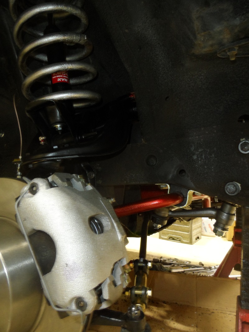 I removed the blower so I could get to the brake lines - and remove the old pressure switch, and found the blower motor doesn't turn, by hand it's hard to turn it, and the bottom of the three bolts was broken off - and has been that way for years judging by the rust. But you can tell the PO didn't give a rip because the heater core is bypassed and I am missing a heater valve. 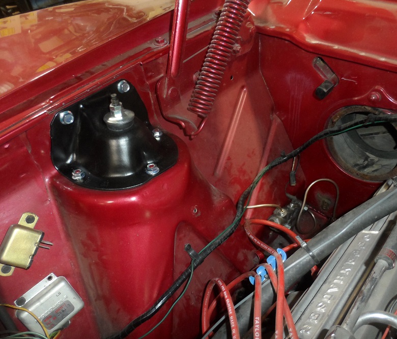 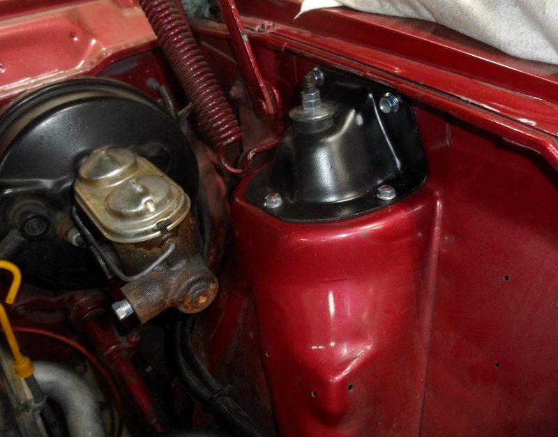 I guess this shows the NOS alternator - one of the pics also shows the NOS regulator I put on a year or so ago. 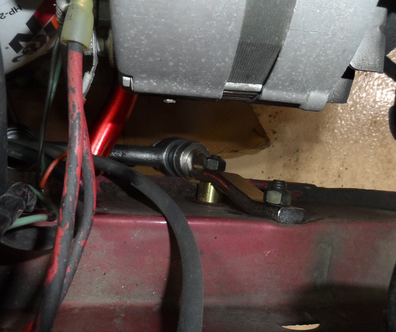 The nickel plated idler arm bracket - it was dirty and slightly rough so it won't look like show chrome... 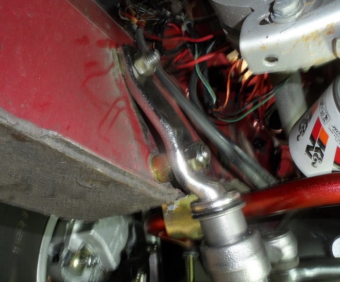 Those calipers are close to the wheels - glad there's no weights there, they'd not clear. Oh, and you can see the crud build-up on the frame and parts - I suspect the PS sector leaks, there's several leaks to take care of. 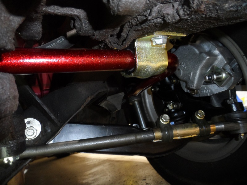 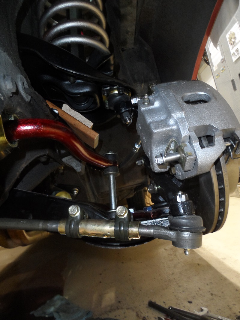 ------------- http://theamcpages.com" rel="nofollow - http://theamcpages.com http://antique-engines.com" rel="nofollow - http://antique-engines.com |
Posted By: purple72Gremlin
Date Posted: Mar/23/2018 at 9:58pm
|
Posted By: billd
Date Posted: Mar/23/2018 at 10:16pm
|
You'd likely have trouble reaching these brake lines - it's hard to tell from the photos but it's one of those lean way in and reach between engine and firewall with a small ratchet and using a lot of patience, remove the screw and clamp......... I'm going to try to go back with new lines in the same place. A lift would have been nice when doing the brake fitting - as I was sitting for that. That's where there was up and down - sit and fit stuff, not yet good enough, get back up again. There's a lot of finger prints on the bumper - luckily it's attached well. Ha. Unfortunately, however, no lift will help in the engine compartment fitting the new lines in there. I'm ok laying down under the car - it's when I get up that menieres hits me and I have to get up certain ways. But I can stay under there as long as needed. Standing is what gets to my back. The doc said all those years as a mechanic, then farming - all that lifting and carrying. I used to lift transmissions to the bench, 4 cylinder engines I lifted onto the bench without help, and loading seed, bailing hay and straw - it has taken a toll and now standing is a problem as is sitting unless it's a seat or chair that's just right. My back has waaaay too much curve - instead of the 30 degrees it should have, it's got 60. And that's caused nerve issues and disk issues. (I asked about grease fittings but we don't have that technology yet, I guess) The front wheels are on and the car is on the ground, making it a Bit easier leaning into the engine area........ the big issue is these fenders, like the Eagle fenders, and the other javelins, they DENT easily. The left fender has a spot that's "dented in" and won't stay popped back up like it should. But who knows what the PO did - maybe the metal is thin on the top of that fender. Luckily I have a NOS left. Wish I could find a NOS right fender, too. I have a different limited slip differential to put under the car but want to go through it first and totally renew the brakes on it before putting it under the car so that project will have to wait a bit. This engine breaks the tires loose pretty easily and it often seems as if it's spinning just one so I question the differential that's under it, so got another twin grip to go through and put under it - some day..... For now, all I need to do is finish up the brake lines, get it aligned and it's on the road again - Oh, need to install the new PC front seat stuff but that's a different thread. ------------- http://theamcpages.com" rel="nofollow - http://theamcpages.com http://antique-engines.com" rel="nofollow - http://antique-engines.com |
Posted By: purple72Gremlin
Date Posted: Mar/23/2018 at 10:39pm
|
Posted By: Lyle
Date Posted: Mar/24/2018 at 6:43am
|
Bill, noticed from your pictures you have a glass fuel filter. There was much discussion of these on this post: http://theamcforum.com/forum/can-not-accelerate_topic92957_post823353.html?KW=glass+fuel+filter#823353
|
Posted By: pit crew
Date Posted: Mar/24/2018 at 6:51am
P.S. I don't care what you say, that is starting to look like a show car. ------------- 73 Hornet - 401EFI - THM400 - Twin Grip 20 |
Posted By: Lyle
Date Posted: Mar/24/2018 at 7:38am
|
Were I first started working at a truck body shop there was a Portuguese Coach Builder by trade. After a hail storm a local dealer asked if could do repairs on dozens of damaged new cars. With a small propane torch, rag and a bucket of water he removed 90% + of the damage. No repaint required. Saved the dealer $$$ in one day. Should have seen the brass inlay horse drawn coaches he made from scratch, wood spoke wheels and all - pure art.
|
Posted By: billd
Date Posted: Mar/24/2018 at 12:16pm
This old clunker? I only drive it when I don't care how I look............ HAHAHA I removed some dents while doing my SX4 body work, prepping it for the final paint, using a torch and a rag soaked in COLD water. Heat the spot and then quench it. In a couple of places I got it flat enough using that and a dolly and hammer GENTLY that I didn't even have to use filler - primer and blocking took care of it. Not sure I want to try it but may see about that spot in that left fender top. I just don't want to mess up the paint even though the car is going to need new paint eventually anyway. ------------- http://theamcpages.com" rel="nofollow - http://theamcpages.com http://antique-engines.com" rel="nofollow - http://antique-engines.com |
Posted By: billd
Date Posted: Mar/31/2018 at 5:29pm
|
Ran the new rear brake line today. The original had a little accident years go when the drive shaft somehow whipped up against the floor at the front and ripped up the line. the PO replaced the brake line roughly from where it jogs over to the tunnel area back to where it comes out of the tunnel to snake back to the differential hose. So there were two unions under there and extra line sort of looped as he obviously used a standard length and ran a slightly different route than stock. I found at least three broken line clips still screwed to the floor below, a couple in the tunnel area. I ran a new single line all the way from the hose at the rear to the union at the firewall and used the factory spots for clips to secure the line. So the steel line to the rear is done. The steel line from the combo valve out to the right front wheel is done. i got a good start on the line from the master cylinder port for the rear brakes over to the combo valve. That one will take perhaps another half hour, then I'll have the line from master port for the front brakes over to the combo valve and the line from the combo valve over to the left front wheel. Getting closer to putting fluid back into the master and flushing and bleeding. Running those lines along the firewall isn't easy - there's a lot of stuff in the way it's hard to get to back of the engine, it snakes around wires and other lines, etc. ------------- http://theamcpages.com" rel="nofollow - http://theamcpages.com http://antique-engines.com" rel="nofollow - http://antique-engines.com |
Posted By: billd
Date Posted: Apr/02/2018 at 2:29pm
|
I'm working on trying to bleed the brakes - so I can move the car around in my shop to swap differentials, and in the process discovered something I wonder if anyone else has run into.,, I have the left front wheel off, the car raised up a bit to make it easier to get to the bleeders, etc. and decided to turn the wheels to the left, bleeder for the left front is on the front and it would then point outward and easier to see and reach. As I turned the steering wheel there was a spot of resistance then a pop then it finished turning. What the heck? Under the car was the left inner tie rod great fitting....... then I looked and noticed the inner tie rods hit the cross member. HUH???????????????? Wait a minute - how could I have screwed that up? So I crawled under the front of the car and looked - nope, I don't have the drag link on backwards or up-side-down (can't anyway, the holes are tapers, it's not perfectly straight, and the end with the greater distance between holes has to go to the idler arm end. I even doubted all of my front end experiences and looked at the Concord, my other Javelin, nope, I wasn't drunk or drugged, and think I was awake, it is correct but man, those inner tie rods can't have grease fittings in them, even PLUGS would smack the crossmember - the area where the engine mount saddles are welded on, those pieces stick forward a bit and are directly behind the inner tie rod ends when the car is sitting straight. What the heck did I screw up? This is embarrassing as heck - I've done more front ends than I care to remember....... and have never ever had anything hit before. ------------- http://theamcpages.com" rel="nofollow - http://theamcpages.com http://antique-engines.com" rel="nofollow - http://antique-engines.com |
Posted By: billd
Date Posted: Apr/02/2018 at 8:52pm
|
Still need to figure out why the inner tie rods all but hit the cross member where the mount areas come down. Geesh it's CLOSE as heck and I can't put a grease fitting in or even a plug on the left side. But I got the brakes bled - at least the front are good and the rear are bled a bit. I did not do the rears very well on purpose. Why, when I'm going to replace the whole differential, brakes and wheel cylinders and the rear hose? So started the car, pulled it out and turned it around so I can get to the back end (shop so full it's hard to work in there now) I pulled the plastic covers off the differential I had stashed in my shop, rolled it around to the middle of the shop on the home-made differential stand and proceeded to remove the steel lines and flex hose off the axle tubes. I pulled the drums and figured I'd need to do some brake work beyond wheel cylinders and to my surprise - the drums are excellent - no ridge at all, and the shoes have at most 10,000 miles on them - if that much. You can still read the whole CoF marks and they have little wear and are very even. I'll clean things up and put the new wheel cylinders on, make the new axle lines, and get it ready to install. I have not checked the ratio on the existing open differential that's under the car. This twin grip is a 3.15 ratio - I marked an axle and the pinion yoke and turned the pinion three turns and not quite a fifth of a turn more and got one turn of the axles. Twin grip made the math easy. It seems to be in good shape and I'm really glad the brakes are this good. No need to turn the drums, etc. The springs that came with it are ok, rusty, but not as bad as those under the car now. So it should sit better and I shouldn't have the trouble with the car going sideways on me when I nail it. This will mean all brake lines and hoses will be new, wheel cylinders new, calipers, pads, etc. up front new, brake hoses new - should be good to go as long as that original combo valve is still operational. That's the only real question now. It started ok, ran good, and the shifter worked fine. MAY need some tweak as far as adjustment, but it worked SMOOTHLY. I have a good NSS/backup switch harness now but need to check the TSM as I can't find the spot on the car to plug it into the harness. Who knows the PO may have removed or taped that up somewhere. It's not where I expected it at all. Not sure what he did to bypass any sort of a NSS - because it starts, that means he's had to have bypassed any sort of switch in order for it to start. We all know if the NSS doesn't work the car won't crank and to get around a bad switch you can jumper it, so somewhere he's got a jumper or twisted wires together to make it crank. Hopefully the TSM will tell me where this should plug in as far as where on the car. ------------- http://theamcpages.com" rel="nofollow - http://theamcpages.com http://antique-engines.com" rel="nofollow - http://antique-engines.com |
Posted By: farna
Date Posted: Apr/03/2018 at 6:02am
|
Do the plugs/grease fittings only hit with the car up off the ground? If so they will clear with weight on the wheels, and if you're flying through the air in a jump you probably won't be turning the wheels...so should be okay. Could check one of the other cars with wheels hanging too... ------------- Frank Swygert |
Posted By: wantajav
Date Posted: Apr/03/2018 at 6:55am
|
Nice job so far BillD Don't let the perfect become the enemy of the good, they say...these are great cars not Pebble Beach Deusenbergs. But are you sure your new parts are the same as the old ones? My inner tie rod ends when the car is sitting on the ground, are not even close to hitting. I can get my whole hand back there. If you want I'll measure the Center-center length of my Pitman and steering arms for ya..(69 car though) Only two things are in play here. Where is the cross member and how far back does the pitman arm/steering arm put the inner tie rod ends. Everything else is fixed by mounting holes.
|
Posted By: billd
Date Posted: Apr/03/2018 at 7:27am
|
Farna - I had thought of that but then the inner tie rod ends never move vertically, only laterally or horizontally because the drag link is supported by the idler on the right and pitman on the left and they move in an arc that isn't quite horizontal - and the inner ends are never allowed to do more than pivot at the drag link. I checked and the old tie rods aren't as "heavy" looking. The parts are a good fit and the MOOG tie rods are heavier made with ends slightly larger. The cross member is held in place by nuts and bolts with tapered heads- in fact a nut and bolt on each end IF IT IS LIKE 1970 - and again, IF IT IS LIKE 1970, the nut is literally a lug nut and the bolt could be called a lug bolt because it's fine thread and a tapered or countersunk head. This means when the bolt and nut are in place on each end it forces the cross member into a perfect position.. You can't slide them back and forth. There's no gap - you can't stick a pinky between tie rod end and the part of the cross member that the engine mounts bolt to. It's the VERTICAL part of the cross member - the saddles for the mounts extend down top to bottom of the cross member. There's a lot more room on the Concord but then it's a 6 and the cross member sweeps back. I looked at my 70 and although the parts look the same, there's more room. I did a google search "javelin tie rods cross member" and got hits- I'm not the first person....... And one solution was "grind the part of the engine mount support that gets hit" I'd not mind a pic, or measurements, or whatever, and can post photos when I get the front end back up on it - right now the car is turned around so I can get to the back and the front is boxed in by the shop door and "stuff". All I can do is stand in front of it. It does appear to be worse with the front wheels up - but then the tie rods are down on the outer ends and the angles of the tie rods change enough .... There's no way to get anything on incorrectly - I have a ton of self-doubt and always have so always question myself and have to either prove myself wrong or right with almost everything I do - and on this I figured hey, can't put the drag link in backwards or the wheels would only turn one direction because of the differences in distance frame to idler and frame to pitman, can't have it backwards, the holes are tapered and things wouldn't go in enough to put the nuts on, nothing is sagging or broken or bent. At this point since I've found others who replaced tie rods and then had the grease fittings hit - I assume the new parts are FATTER and clear differently. ------------- http://theamcpages.com" rel="nofollow - http://theamcpages.com http://antique-engines.com" rel="nofollow - http://antique-engines.com |