Headlight switch problem for the true electrical g
Printed From: TheAMCForum.com
Category: The Garage
Forum Name: Electrical - non engine
Forum Description: Charging systems, lights, non-ignition system, it goes here.
URL: https://theamcforum.com/forum/forum_posts.asp?TID=86328
Printed Date: Apr/23/2024 at 3:51am
Software Version: Web Wiz Forums 12.03 - http://www.webwizforums.com
Topic: Headlight switch problem for the true electrical g
Posted By: Cornelius Rambler
Subject: Headlight switch problem for the true electrical g
Date Posted: Mar/23/2017 at 2:52pm
|
First let me say that this is NOT a problem with my AMX. Well...sorta. If I solve this problem, I can finish up the loose ends on THIS project and sell it so that I will have the funds to finish my AMX! So, PLEASE bear with me... I'm trying to convert the hide-away headlights on my '67 Cougar from the original vacuum motors to electric. On one end I have a simple headlight switch. On the other end I have two linear actuators (One per headlight door...) each with a built-in limiter switch that extends/retracts by reversing polarity of the two wires. What I need is a means of operating the two motions using the headlight switch. Somewhere in the middle I need to place two of these:    This was put together several months ago by my old boss and good friend Jerry. Since I am very electrically challenged I asked him to show me how to install it in the car. He asked me if I was actually ready at that point and I said well, no. He told me he would help me when I was actually ready for it. Now I'm ready but I'm about 4 months too late as Jerry passed away in December. So, now I'm reaching out to some of the most prolific and brightest auto electrical minds on the internet. I can really use your help... BTW the relay parts he used were NTE R14-11D10-12 & R95-110 Brian (Cornelius Rambler)  |
Replies:
Posted By: 304-dude
Date Posted: Mar/23/2017 at 3:24pm
|
Off topic, the best electric system for head lights were on my 65 Riviera. Both lights opened together synchronised by a shaft system very much like a windshield wiper transmission. The only difference is length of rods and the motor was the same used in power windows and seats. And hid in the confines of the bumper. Since it was a one year production, you may never see every detail on setting one up, up close. No need for timing just convert a ford wiper motor and modify the wiper transmission to use lever opening doors. Very simple and easy to maintain. Problem with electic doors done by timers, is after time the doors require more time to open and to close by wear and tare on the motors, plus you get one eye open syndrome when a timing circuit fails. I would use a simple two way slide switch to place swap power lead to motor, with ground when open. This way no timing contol is needed. Plus to close power muct be switched to what was originally ground to reverse the motor. If you want a controller to time open and closing I made one... for my Honda Accord Coupe. It is VCM with a custom setup to make a manual performance intake manifold work without the ECU to control when to open and close. To open or activate the motor, a simple 12v signal is needed. To close, the signal is switched off. Once closed no power is sent to the motor, or motors. Very simple and effective. Plus the parts are easily obtainable at Fry's or Radio Shack, or a big distributor such as Digi key. Can post my timing circuit to activate a motor or driver relay for more than one motor. ------------- 71 Javelin SST body 390 69 crank, 70 block & heads NASCAR SB2 rods & pistons 78 Jeep TH400 w/ 2.76 Low 50/50 Ford-AMC Suspension 79 F150 rear & 8.8 axles Ford Racing 3.25 gears & 9" /w Detroit locker |
Posted By: Cornelius Rambler
Date Posted: Mar/23/2017 at 10:31pm
|
"If you want a controller to time open and closing I made one... for my Honda Accord Coupe. It is VCM with a custom setup to make a manual performance intake manifold work without the ECU to control when to open and close. To open or activate the motor, a simple 12v signal is needed. To close, the signal is switched off. Once closed no power is sent to the motor, or motors. Very simple and effective. Plus the parts are easily obtainable at Fry's or Radio Shack, or a big distributor such as Digi key. Can post my timing circuit to activate a motor or driver relay for more than one motor." I'd appreciate it. While I'm still hoping that someone will see this and can decipher where my buddy Jerry was going based on the pix above, help of any kind is greatly appreciated!
|
Posted By: Lyle
Date Posted: Mar/24/2017 at 6:21am
|
Posted above are relays that I "assume" would be put on the headlight circuit to power the headlight cover motors. One relay double throw would be set up to to open and close depending if power from the headlights was on or off. The other two relays would power each motor and would likely have individual limit switches in circuit for determining open and closed. You need two motors and four limit switches as each side will drive at different speeds and eventually the system would have one side out of sink if you did not wire this way. I believe the Riviera had one motor that used an internal AMP limiter to determine open and closed limits. Hope this helps.
|
Posted By: Lucas660
Date Posted: Mar/24/2017 at 6:59am
| I assume that the actuators have only 2 wires? The limit switches should have diodes in series inside. The relays should change polarity depending if the headlamps are on or off. If you can verify the wiring for the actuators I could draw a diagram for you. |
Posted By: Cornelius Rambler
Date Posted: Mar/24/2017 at 12:02pm
Thanks! And yes, to clarify, the actuator has two wires...YELLOW & GREEN. Applying power to the YELLOW and connecting ground to the GREEN retracts the actuator piston thus opening the headlight door. Reversing and applying power to the GREEN and ground to the YELLOW extends the piston and shutting the headlight door. Luckily, the 2" throw between the fully extended and the fully retracted actuator piston mimics the throw of the original vacuum motor rod. So, the preset shut off of the limit switch in either direction works just fine! So there 'ya go. Thanks and thanks to everyone that has responded to this thread! |
 Lucas660 wrote:
Posted By: Lucas660
Date Posted: Mar/24/2017 at 3:02pm
This will work if you replace ignition with the headlamp feed. Stolen from a Hyundai forum but the same principle applies. You could run the constant 12v feed from ignition switched but you would have to make sure the headlamps are switched off before switching off the ignition.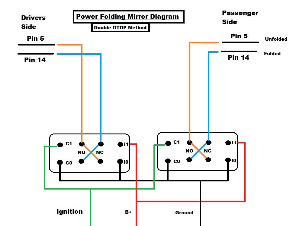
|
Posted By: Cornelius Rambler
Date Posted: Mar/24/2017 at 3:30pm
Posted By: 304-dude
Date Posted: Mar/24/2017 at 3:31pm
|
Problem is you cant use your headlights when ignition is off. IIRC, the headlight switch should have a constant 12v source. That should be tapped to the motor drive relays. The output of the headlight switch should be what drives the relay switch to open the doors. In principle the head lights will light up and activate the doors simultaneously. When the lights go out, the doors close. Very safe and will work like the Riviera light setup and many other door type head lights. Not familiar with the relays so I cannot say how they wire up, let alone how they interconnect with the open and close sensors you are using. ------------- 71 Javelin SST body 390 69 crank, 70 block & heads NASCAR SB2 rods & pistons 78 Jeep TH400 w/ 2.76 Low 50/50 Ford-AMC Suspension 79 F150 rear & 8.8 axles Ford Racing 3.25 gears & 9" /w Detroit locker |
Posted By: Cornelius Rambler
Date Posted: Mar/24/2017 at 3:32pm
|
Thanks Lucas! Question: The B+ is sourced from where? Brian
|
Posted By: tsanchez
Date Posted: Mar/24/2017 at 4:23pm
|
That should be no problem with those two relays, I can t right now but I will try monday to make up a wiring diagram for you ------------- http://s192.photobucket.com/user/antonsan/media/jav1_zps87a70dce.jpg.html" rel="nofollow"> 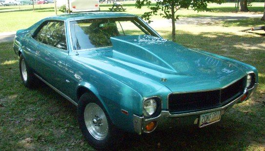
|
Posted By: tsanchez
Date Posted: Mar/24/2017 at 4:36pm
http://s192.photobucket.com/user/antonsan/media/20170324_153444_zps4hlyvvrw.jpg.html" rel="nofollow">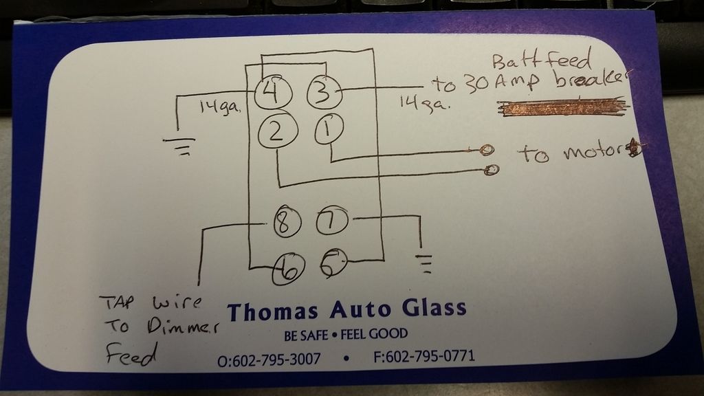
------------- http://s192.photobucket.com/user/antonsan/media/jav1_zps87a70dce.jpg.html" rel="nofollow">
|
Posted By: Lucas660
Date Posted: Mar/25/2017 at 6:53am
Spot on Tony. And for 304 dude this is how I assume the internals of the actuator function. 
|
Posted By: 304-dude
Date Posted: Mar/25/2017 at 7:22am
|
Ah, so it has limiting switches internal. That makes it cleaner. Your diagram looks wrong... The motor should have one lead to one relay and the other lead to the second relay. What happens is when the circuit is not used, both relays should have ground at both motor terminals. Using the switched power from the head light switch will activate the motor through the circuit between the internal switches of the relays. Once the limit has been reached, both terminals to the motor are positive 12 v. When the headlight switch is off... The motor receives ground from the relay switch that has no power. Once limiter has been set, the internal switch will set ground back to the motor. The limiter switches control toggling like two on off switches, when one is off the other is on so to speak. Just a matter of knowing what switch is doing when the relay is active and when the limit has been reached, and visa versa. Now that I know... I will post a diagram on how it should hook up. ------------- 71 Javelin SST body 390 69 crank, 70 block & heads NASCAR SB2 rods & pistons 78 Jeep TH400 w/ 2.76 Low 50/50 Ford-AMC Suspension 79 F150 rear & 8.8 axles Ford Racing 3.25 gears & 9" /w Detroit locker |
Posted By: 304-dude
Date Posted: Mar/25/2017 at 8:56am
Geezo, I mistook that the relays had been separate single pull single throw and they had a limiter built in... your diagram is correct for the function. And are simple enough to setup. Though I did come up with a simple diagram to use standard automotive relays which are pretty robust in ruggedness. The ones you pictured seem like for indoor use. My diagram would be correct only if you had chosen two separate automotive relays not a combination relay for each lamp door. If anyone is interested in my diagram I will post it. But I feel I have already done enough distraction with my rambling. ------------- 71 Javelin SST body 390 69 crank, 70 block & heads NASCAR SB2 rods & pistons 78 Jeep TH400 w/ 2.76 Low 50/50 Ford-AMC Suspension 79 F150 rear & 8.8 axles Ford Racing 3.25 gears & 9" /w Detroit locker |
Posted By: Cornelius Rambler
Date Posted: Mar/25/2017 at 11:01am
|
WOW! THANKS GUYS!!! Now is there a consensus that the diagram that Tom posted is correct for my application? Also, can someone explain how this works without wiring to the ignition switch itself? I assume that how the dimmer switch functions overall is the key here. (Not questioning...learning.) Brian
|
Posted By: 304-dude
Date Posted: Mar/25/2017 at 11:13am
|
Just use the head light switch... it should have 12v always on and 12v switched. The 12v switched should activate the relay and start opening the doors. 12v always on should be at the inputs of the relays. When you turn off the lights at the switch, the relay closes to its at rest position, which allows the motors to reverse and stop when limit switch has tripped. But it all requires syncing which way the motor opererates in. So 50/50 it will be correct, or try to close when you are expecting it to open. Simple fix is to swap power leeds to motor. Now for the big question... because I started nay saying I kept this asside as I wanted to keep the wiring portion still in play, not what parts are used and limitations. My question is are those limit switches able to handle power loads or are they meant to activate relays. My understsnding is motors are best driven by relays directly. Switches are to actviate relays. That is the main reason why I questioned how things are hooked up to function. Just being careful as to how much reliability you want for your customization. ------------- 71 Javelin SST body 390 69 crank, 70 block & heads NASCAR SB2 rods & pistons 78 Jeep TH400 w/ 2.76 Low 50/50 Ford-AMC Suspension 79 F150 rear & 8.8 axles Ford Racing 3.25 gears & 9" /w Detroit locker |
Posted By: tsanchez
Date Posted: Mar/25/2017 at 11:35am
|
B+ should come directly from battery through a 30 amp circuit breaker, light switch feed cannot handle the amperage needed. Just use my diagram X2 . ------------- http://s192.photobucket.com/user/antonsan/media/jav1_zps87a70dce.jpg.html" rel="nofollow">
|
Posted By: tsanchez
Date Posted: Mar/25/2017 at 11:38am
|
Dimmer switch just toggles power from light switch to hi and lo beams, so it has one wire in from switch then when you push on dimmer it either sends power to low or hi beams, thats why you feed relay coil circuit from input side of dimmer(easier to access) the doors and lights will operate with or without key on just like all cars. ------------- http://s192.photobucket.com/user/antonsan/media/jav1_zps87a70dce.jpg.html" rel="nofollow">
|
Posted By: Cornelius Rambler
Date Posted: Mar/25/2017 at 1:53pm
AH HA!!! OK...I think I got it. Thanks again Tom! Brian
|
Posted By: Cornelius Rambler
Date Posted: Mar/25/2017 at 1:58pm
|
Wanna' thank everyone for the help. Now all I gotta do is put this together and make it purty. It really is a nice car and I hate like sin to sell it. But, I can't afford two cars at this time in my life and the Cougar is only my second favorite car! THANKS AGAIN! Brian (Cornelius Rambler) |
Posted By: tsanchez
Date Posted: Mar/25/2017 at 10:19pm
|
You are welcome, it's Tony though, haha ------------- http://s192.photobucket.com/user/antonsan/media/jav1_zps87a70dce.jpg.html" rel="nofollow">
|
Posted By: Cornelius Rambler
Date Posted: Mar/27/2017 at 7:16pm
CR@P! Sorry Tony...thanks again!!!
|
Posted By: Cornelius Rambler
Date Posted: Apr/20/2017 at 4:21pm
OK... Wired everything as diagrammed on my desk. Without installing, how should I test the system? I DID combine the two grounds (Post 4 & 7) with the lead to be tapped into the dimmer switch (Post 8) using the ground from my charger. I attached the positive lead (Post 3) to my 30 amp breaker and out to the positive on my charger. Lastly, I touched the leads to the actuator (Post 1 & 2) to the actuator wires themselves and activated the piston. Switching the leads around caused the piston to move in the opposite direction. Is there a way to simulate the switching from one direction to the other through the relay without actually tapping the #8 lead to the dimmer switch? Thanks in advance...AGAIN! Brian
|
Posted By: tsanchez
Date Posted: Apr/21/2017 at 9:24am
|
if wired like I showed, all you do is provide 12v to pin 8 and it will operate motors, then when you remove power it will reverse. 4 and 7 are grounds not to be combined with 8 which is switched 12v ------------- http://s192.photobucket.com/user/antonsan/media/jav1_zps87a70dce.jpg.html" rel="nofollow">
|
Posted By: tsanchez
Date Posted: Apr/21/2017 at 9:40am
|
I would guess you see that 3 is constant 12v and is also linked to 6 so 3 and 6 are same 12v constant, also 4 and 5 are linked and are ground ------------- http://s192.photobucket.com/user/antonsan/media/jav1_zps87a70dce.jpg.html" rel="nofollow">
|
Posted By: tsanchez
Date Posted: May/05/2017 at 5:06pm
|
Oops, I screwed up the diagram, move motor leads to 5 and 6 and link 1 and 4 together and 2 and 3 together and it should work. lol ------------- http://s192.photobucket.com/user/antonsan/media/jav1_zps87a70dce.jpg.html" rel="nofollow">
|
Posted By: Cornelius Rambler
Date Posted: May/06/2017 at 7:44pm
|
HOT DANG TONY! IT WORKS!!! If you're ever in our neck of the woods I owe you dinner! By the way, do you know of a Paul Arnold? REALLY good upholsterer in Chandler. I think. Anyway, thanks again!!!!!! Brian
|
Posted By: tsanchez
Date Posted: May/07/2017 at 10:16pm
|
No I dont know him, I'll take a dinner if I am ever out there ------------- http://s192.photobucket.com/user/antonsan/media/jav1_zps87a70dce.jpg.html" rel="nofollow">
|