1967 AMC rebel wiring with new alternator?
Printed From: TheAMCForum.com
Category: The Garage
Forum Name: Electrical - non engine
Forum Description: Charging systems, lights, non-ignition system, it goes here.
URL: https://theamcforum.com/forum/forum_posts.asp?TID=100380
Printed Date: Apr/16/2024 at 1:01pm
Software Version: Web Wiz Forums 12.03 - http://www.webwizforums.com
Topic: 1967 AMC rebel wiring with new alternator?
Posted By: Dustintf522
Subject: 1967 AMC rebel wiring with new alternator?
Date Posted: Jun/05/2019 at 9:21pm
Hello everyone!  I'm terribly sorry I know this question has been asked/beat to death. Going from a Motorola to a Remy (20169) I'm just making sure I've got everything wired correctly. I've got the green, and orange wire going to the 1 and 2 slots, The main battery wire from the loom going to the big red junction on the back of the alt, as well as the ground going to the ground bolt. Question. After reading what I could find. I need to disconnect the original voltage regulator. Only use the orange wire as it currently is, connected to the #1 slot (exciter wire?)(I still want the dash light to function) For the second terminal use a new wire and run it from the 2nd slot on the alt. To the starter relay (where the positive battery terminal connects) I'll give this a go in the morning, I'm just getting my butt handed to me!  Anyone with more information, it's more then appreciated!
 ! ! |
Replies:
Posted By: billd
Date Posted: Jun/05/2019 at 10:44pm
|
That isn't a GM alternator model number so it must be some remanufactured unit? At what, about 60 amp? (a 55 amp Motorola would do the same thing more easily, but whatever.......) Did you happen to see this? http://theamcforum.com/forum/wiring-a-gm-10si-or-27-si-into-amc_topic12493.html" rel="nofollow - http://theamcforum.com/forum/wiring-a-gm-10si-or-27-si-into-amc_topic12493.html Alternator output should go to the battery side of the starter relay on the fender if it's a Ford style starter. Don't touch the larger red wires in the loom. Output of the alternator should go to a point that connects directly to the battery - that's normally the starter relay/solenoid in the fender on Ford starter equipped AMCs. You won't use the green wire that went to the Motorola as that comes from the Motorola regulator. You won't use the black wire that went to the Motorola alternator as that's the ground for the Motorola regulator and nothing do with with grounding the alternator. You don't need a separate ground for the alternator - it grounds via the brackets to the block - which carry a bigger load than any little ground wire would. When you bolt the alternator to the engine - it's grounded to the engine. HOWEVER, make sure the factory ground from the block to the chassis or cross member is there and good and solid. Yes on running a wire from sense on the alternator to the battery side of the starter relay. This way it senses from where the rest of the car takes the load from. -------------  http://theamcpages.com" rel="nofollow - http://theamcpages.com http://antique-engines.com" rel="nofollow - http://antique-engines.com |
Posted By: Trader
Date Posted: Jun/06/2019 at 10:50am
|
Agree with Build on all points except the ground wire for the alternator. Have come across so many with real pretty powder coated brackets that are excellent at insulation. If you have powder coated brackets or even a powder coated alternator, ground it! I tend to run a ground wire now anyhow as it seems to reduce galvanic corrosion between alternator and fasteners. My opinion.
|
Posted By: billd
Date Posted: Jun/06/2019 at 11:53am
|
When I powder coat - I mask areas of contact that can be electrical paths. The ground wire can't hurt anything - so if a person feels or wants - there's nothing that can be said like "don't do it!" because there's just no science against it. If you have paint or powder coating that can interfere - by all means. I tend to keep electrical contact areas very clean and smooth. I clean and plate bolts, and when I restore an alternator, I ensure that the path between front frame, stator core and rear frame is electrically sound - in other words, I spend the time and CLEAN those areas of contact so it's not relying only on the through-bolts for electrical path - as often those rust or the zinc oxidizes. If you are getting "galvanic corrosion" then there's a path that has some sort of resistance - otherwise the potential between the parts should be 0 - they should be electrically identical. You may notice that Chrysler does have a ground between the Denso alternator and the battery and block. The ground wire from the battery goes to block and alternator and chassis. It's a complex ground wire. Now to avoid confusion - the black wire going to a Motorola alternator is NOT! the alternator ground - it's the REGULATOR ground. Motorola regulators are NOT grounded via the case - they are grounded directly to the alternator so that in cases of the alternator, chassis, etc. having different potentials, the regulator won't see a low voltage and try to increase output. This way the regulator ground is identical to the alternator ground regardless of what else happens - and this should be a clue for folks having some issues - that black regulator ground that goes to the alternator is critical - it must be clean and tight. When I say if you convert you don't need that ground wire - I'm saying you don't need it because it grounds a regulator you will no longer be using. I suspect a ground wire for the alternator to the block and chassis is more important for high output systems than the 35 amp and 55 amp Motorola systems - but again, there's not a valid reason to not run a ground on any system. Just keep them all clean and tight - you can NOT tell by looking - you must remove them to know for sure or use a Fluke or similar sensitive meter to measure voltage drop on the grounds. I know in auto sound systems - the pros that helped me with my Alpine contest system were against a ground from every single thing - they were concerned about ground loops..... but that's a bit different. ------------- http://theamcpages.com" rel="nofollow - http://theamcpages.com http://antique-engines.com" rel="nofollow - http://antique-engines.com |
Posted By: Dustintf522
Date Posted: Jun/10/2019 at 9:46pm
|
I'm sorry I had the wrong information posted! The only difference between the old one and new one, would be the red plate. This one has two dies, and the orginal one only had one. 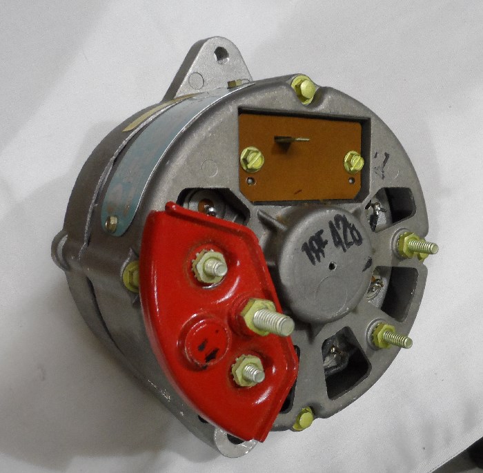 Old one. My question is, do I need to swap the single die over to the new alternator at the same place as the old one? The only way the alternator is charging currently is will a jumper wire from the aux (organe wire) to the power wire (red) I'm terrible with wiring, I tried following the forums but to no avail. The green wire goes to field (brushes) The orange wire is the aux (used to connect to the post closest to the red terminal) (now connects to the bolt that connects to the side of the red post) Black is grounded on other side of the post (across from the orange wire) Anything im doing wrong or do I just need to swap the red plates? So that the terminals are on just one side? Also the alt light is on when the car is off, and it goes away when you turn it to run, and the oil light comes on. (I've probably got one wore crossed and I cant figure it out ) 😂 And thank you all for replying, its awesome and not to mention even better when it saves a couple bucks not having to run to the mechanic for everything! New one 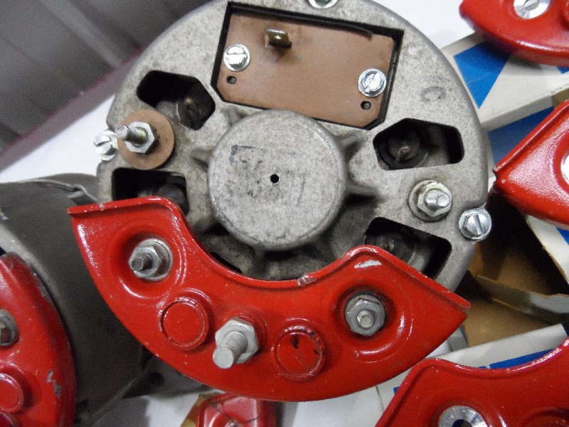 |
Posted By: billd
Date Posted: Jun/10/2019 at 10:02pm
|
NO! Do not swap any parts. The one with the single isolation diode in the plate was a 35 amp. The 40 and 55 amp alternators have the two isolation diodes in the heat sink (red plate) because of the extra current carrying requirements - it takes more diodes to handle more current output. What do you mean the only way it is charging is by a jumper from the orange wire terminal to the output terminal? What voltage are you reading?? The voltage coming from the terminal for the orange wire should be close to FIFTEEN VOLTS - that's over-charging. The output from the output terminal on the isolation diode should be "about" 14 volts. We need to know what voltage you are reading from the orange aux/regulator terminal and what voltage you are reading at the output terminal of the isolation diode. What made you say it wasn't charging - how did you come to that conclusion? ------------- http://theamcpages.com" rel="nofollow - http://theamcpages.com http://antique-engines.com" rel="nofollow - http://antique-engines.com |
Posted By: Dustintf522
Date Posted: Jun/10/2019 at 10:08pm
|
Will post voltages tomorrow! Again thanks for the quick reply!
|
Posted By: Dustintf522
Date Posted: Jun/11/2019 at 11:50am
|
Output (red) 12.14v Aux (orange) 13.38v Field (green) 5.80-6.20v And the ground was grounded. With the orange and red wire both connected the voltage goes to about 12.7v to the battery. I'm probably doing it backward. Haha.
|
Posted By: Dustintf522
Date Posted: Jun/11/2019 at 2:11pm
|
Hmm, it seems I found out the issue. The battery was in such a low charge that even bridging the wires couldn't overcharge/keep up with the engine. I took the jumper wire that was one red and orange off. I gave it about 30 minutes of cruise time, (yes I know it puts strain on the new alt) and my other testing was only done at idle. When I got back from driving, I tested it was sitting about 12.5 and creeping up. Slowly. So for now I'll keep a close eye on the battery and see if I have any more issues! You guys have been awesome, and helpful! Thanks for the tips! |
Posted By: billd
Date Posted: Jun/11/2019 at 3:00pm
|
Find/buy/borrow/trade,whatever, get a good battery charger on that thing for at least 12 hours. Then check the battery state of charge. If it's not at 12.6 with a good charger for that long, it's not going to take. Fully charged JUST off the charger there will be a surface charge - it may read as high as about 12 volts. Turn the headlights on for 20-30 seconds - engine NOT running, let it sit a couple seconds or so then check battery voltage again (engine NOT running, charger off and disconnected) A fully charged GOOD battery should read 12.6 volts when charged with the surface charge off. If you can't get that, you've found your issue.......... Good luck! ------------- http://theamcpages.com" rel="nofollow - http://theamcpages.com http://antique-engines.com" rel="nofollow - http://antique-engines.com |
Posted By: 67rebel232
Date Posted: May/09/2022 at 1:57pm
I i have a question regarding the exciter wire. Where is this wire located?? What color is the wire??? I have a 1967 rambler rebel 770 someone please help 
|