
|
|
|
Your donations help keep this valuable resource free and growing. Thank you.
|
Need help with a wiring challenge |
Post Reply 
|
Page 12> |
| Author | |
zeebo76 
AMC Apprentice 
Joined: Oct/09/2019 Location: Washougal, WA Status: Offline Points: 158 |
 Post Options Post Options
") Thanks(0) Thanks(0)
 Quote Reply Quote Reply
 Topic: Need help with a wiring challenge Topic: Need help with a wiring challengePosted: Oct/19/2019 at 12:20am |
|
So I'm working on making a diagnostics box like the one shown here:
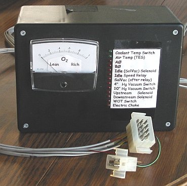 It'll be some form of container attached low on the dash to display the running status of my '86 Eagle while I'm driving. However, I don't want it on all the time, I'd like to be able to have it switchable. The issue here is that I want to be able to switch all 20-ish inputs with one switch. Toggle it on, the whole box lights up and shows that things work. Toggle it off, the box is disabled again. I'm sure this is a simple problem, but for some reason I can't wrap my head around it! Any help would be appreciated.
|
|
 |
|
|
tomj
AMC Addicted 
Joined: Jan/27/2010 Location: earth Status: Offline Points: 7544 |
Post Options
Thanks(0)
Quote Reply
Posted: Oct/19/2019 at 1:32am |
|
you probably don't need to disconnect the leads if the box is powered off. but i'm not familiar with eagles at all. i take it this is some diagnostic port? i can (barely) make out the label; vacuum switches, some solenoids, etc. if each of those are devices within the Eagle electrical system, and they're on and operating as i assume they are, the "state" of each of them, on or off (0V, or 12V, as the case may be), or some varying voltage (air temp?), each of those signals goes to some input circuit inside your box. what are those inputs? the fairly universal approach -- i use that word intentionally! -- is to have inputs on devices (like yours) be "no load", or negligible load, on the thing under test/measurement. for example, if you're monitoring some solenoid's operation, that solenoid's operating environment is some voltage and current AMC chose, probably 12V, at an amp or two or three. but your circuit cannot interfere with that! instread of reaching in and grabbing it, metaphorically, it reaches in and gently applies a finger... so your input circuit should be buffered from the thing under test. for a solenoid -- probably any solenoid, big or small -- if you drew 20 mA out of it i'd be willing to bet that would be "negligible". 20mA powers an LED just fine. the "correct" way, a better but more complex way, is to buffer the thing under test with an active circuit that translates whateveritis you are measuring into some internal signal. say, a circuit that translates 0V, 12V, into 0V, 5V, that runs LEDs, meters, etc. then you turn off the power to the buffering electronics and the output goes off. if you wire say an LED directly to the solenoid, that's safe and easy -- but yeah the LED is on all the time and yeah, you;d need a switch contact pair to disconnect it. "things should be as simple as possible, but no simpler". Einstein said that. it applies here. you may need to add more complexity to do things that seem conceptually simple, like putting circuitry in series with each sensor. as you suspect, you are unlikely to find a 20-pole switch. there are 20, 50, 100 pole relays, but you dont want to go there... it will become crazy fast. though i'm mentioning it last, the first thing i'd do is sit back and decide what it is you want to display, and why. some things may warrent a dedicated sensor and LED, but do you reall yneed to monitor all of them all the time? maybe you'd be better off grouping them, and using a multi-position rotary switch to connect an LED to one of 4, 5, 6 devices. (add a 5, 6, 7th position that wires the LED to NOTHING -- that turns it off). the O2 sensor warrants its own display -- but you know that cuz you dedicated the meter to it. it will probably bounce around a lot. have you put a low-pass filter on it? resistor and capacitor? that'll smooth the bumps down. ideally the meter would read "0" all the time, except when you blip the throttle, let off the gas, etc. |
|
|
1960 Rambler Super two-door wagon, OHV auto
1961 Roadster American, 195.6 OHV, T5 http://www.ramblerLore.com |
|
|
|
|
bigbad69
Supporter of TheAMCForum 

Joined: Jul/02/2007 Location: Ottawa, Ont. Status: Offline Points: 6668 |
Post Options
Thanks(0)
Quote Reply
Posted: Oct/19/2019 at 12:24pm |
|
Tomj pretty much covered the electrical, but I would be concerned with your panel layout. That's a lot of small print to take in while driving. How would you determine which LED is on without concentrating on the panel i.e eyes off the road? The O2 meter is good though. Easy to read with a glance.
|
|
|
69 Javelin SST BBO 390 T10
|
|
|
|
|
zeebo76
AMC Apprentice
Joined: Oct/09/2019 Location: Washougal, WA Status: Offline Points: 158 |
Post Options
Thanks(0)
Quote Reply
Posted: Oct/19/2019 at 1:31pm |
|
That panel isn’t mine, it’s an example from a website that goes over how to make one for the 258 I6 diagnostic port. Mine would be laid out better, and eventually I’d have memorized the sequence of lights. “This one should be on while I’m driving, this one should be off, this one should be on, this one should be off”, etc. the only time I’d actually have to read the words on the panel is if I see something wrong - and I’d try to read it at the safest possible time.
|
|
|
|
|
billd
Moderator Group 
Forum Administrator Joined: Jun/27/2007 Location: Iowa Status: Offline Points: 30894 |
Post Options
Thanks(0)
Quote Reply
Posted: Oct/19/2019 at 6:23pm |
|
I actually have several military surplus relays that have several sets of switches in them........... I wonder what the max is that I have. They are from the 1960s I believe. They are about the size of old radio tubes in some cases.
If some of those share a common ground, can't you just open the ground? Leave the inputs connected? |
|
|
|
|
tomj
AMC Addicted
Joined: Jan/27/2010 Location: earth Status: Offline Points: 7544 |
Post Options
Thanks(0)
Quote Reply
Posted: Oct/20/2019 at 11:59pm |
|
to make the LED arrangement more meaningful, DONT put them all in neat rows. group them by function, and but boring mundane stuff at the bottom, alarms at the top. or high, medium, low, in vertical lines. asymmetry is better. use different color LEDs. make color mean something; red as alarm, green normal, yellow caution. blue cold, red hot. don't label each LED, label groups, mark each LED H, M, or L. mix it up! this is U.I. design 101! lol draw it out on paper first, it's easier than moving holes. |
|
|
1960 Rambler Super two-door wagon, OHV auto
1961 Roadster American, 195.6 OHV, T5 http://www.ramblerLore.com |
|
|
|
|
billd
Moderator Group
Forum Administrator Joined: Jun/27/2007 Location: Iowa Status: Offline Points: 30894 |
Post Options
Thanks(0)
Quote Reply
Posted: Oct/21/2019 at 9:07am |
|
When I was part of the team working on the design for our state agency client database, etc. NOTHING was done until the design and layout was dealt with. We had months worth of meetings.
It was determined what was critical, what was important, what was required by law - then the elements that had to be presented first, on the first page were decided. THEN we laid out the pattern or design of the screens. There was a name for that, can't recall it now, but it was where would things be - on each and every screen. People "expect" things to be laid out in certain ways - the brain controls that, not you. The same thing can be applied to accessories for cars (although auto designers still don't get it - they keep moving things around, no consistency, no rules)
What's most important - all related elements together - and keep in mind the eye scans normally side to side, not up and down. Lights in a vertical pattern - nope - horizontal, in rows - not one long row. Takes too much time to scan looong rows and vertical columns are worse - you want your eyes to find something fast and not be distracted trying to count over 8 lights to determine what's what. I disagree with tom on the vertical thing - eyes move normally side to side. Up and down isn't normal movement. You note that computer screens grew not up and down, but sideways. Radio dials, the tabs of a browser - displayed left to right across the top, etc. But SHORT rows. There's a reason newspapers are in columns! Short rows. Follow the lead of the old-fashioned newspaper. Short rows, in columns. And yes, group 'em. OF course you will be displaying things you'll likely not really care about - use only what's important - do you REALLY need to constantly display everything? |
|
|
|
|
bigbad69
Supporter of TheAMCForum
Joined: Jul/02/2007 Location: Ottawa, Ont. Status: Offline Points: 6668 |
Post Options
Thanks(0)
Quote Reply
Posted: Oct/21/2019 at 3:33pm |
|
It's what's known as system design. Figure out what you need, make it easily accessible, then implement it.
|
|
|
69 Javelin SST BBO 390 T10
|
|
|
|
|
mmaher94087
AMC Addicted

Joined: Apr/01/2008 Location: Arizona Status: Offline Points: 1690 |
Post Options
Thanks(1)
Quote Reply
Posted: Oct/21/2019 at 9:59pm |
|
Then update it with revisions until it fails and bring out Version .2 and sell it again to the poor blokes that bought Version .1.
|
|
|
Mike
|
|
|
|
|
zeebo76
AMC Apprentice
Joined: Oct/09/2019 Location: Washougal, WA Status: Offline Points: 158 |
Post Options
Thanks(0)
Quote Reply
Posted: Oct/22/2019 at 10:00pm |
|
So what I was thinking is that I'd purchase and use a plastic electronics box from Amazon. Got one on the way today, it's about 7 inches wide, 2 inches tall, and 3 inches long. I'll have a total of three new sets of molex connectors for the whole project - essentially, there will be a wiring harness that will be disconnectable from both the diagnostics box and from the ports under the hood.
The box will be self-contained. The switch, all the relays for the switch, all the LEDS, and the O2 sensor gauge will all be in/on the box as required. If I need to take the box out, I just unplug it and pull it off the velcro I'll have on top of the dash to hold it in. AO and BO, the stepper motor signals, will be in their own area and easily digestible at a glance. The other sensor signals will be assorted in order of importance, and red and green will be my LED colors of choice - green LEDs will be for signals that should be on while driving/warm, therefore the LED will be energized while driving. Red will be for signals that should be OFF while driving/warm, and so while I'm driving, if I see RED, I'll know there's probably something wrong. I also purchased a breadboard for all of this, that I'll be trimming for size to fit neatly inside the box. I'll probably set it with small dabs of RTV at each corner, so I can easily pull it out if needed. By the end of it I'll have a neat and tidy little package that can easily be removed and disassembled/troubleshooted if required. As for my supplies - I purchased 25 absolutely TINY SPST relays for this project. Each circuit for each sensor input will go as follows - molex connectors with attached harness will plug into the connectors under the hood. The wires lead to the box, where another set of matching molex connectors make another detachable harness at the box. Each individual wire will lead to its own resistor before the relay, then moving onward through a diode, and then to ground. There will also be a switch to activate/deactivate all relays, therefore making the box fully switchable. It will all be wired in 26GA, and switch power will originate from IGNITION ON power from the fuse panel. As much of this as possible will be attached directly to my purchased and trimmed breadboard, and what is going to be attached to the box will have removable connectors. I've been thinking about venting the box, maybe having a little switch-activated fan in it to help vent heat, but... We'll see how much heat is actually generated. About your question on needing to display EVERYTHING, bill - I really don't need to display everything, but it would make me more comfortable knowing that I have every diagnostic input I need right at my fingertips while driving. All I have to do is reach up and flick a switch - if I see that everything's good, flick it back off, or maybe keep it on. Having all those little flickering lights makes me feel like a fighter pilot or an astronaut!
Edited by zeebo76 - Oct/22/2019 at 10:14pm |
|
|
|
|
Post Reply
|
Page 12> |
 Tweet
Tweet
|
| Forum Jump | Forum Permissions You cannot post new topics in this forum You cannot reply to topics in this forum You cannot delete your posts in this forum You cannot edit your posts in this forum You cannot create polls in this forum You cannot vote in polls in this forum |


 Click for TheAMCForum Rules
 Topic Options